This post:
https://openinverter.org/forum/viewtopic.php?f=10&t=575&start=10#p7771
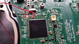
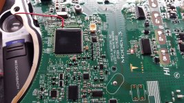
notes that it is possible to use the reset pin of the CPU of an OEM inverter to disable that cpu, to allow wiring in an external brain control, presumably without having to hack at the traces and wiring (as much, at least, and hopefully not at all) of the inverter/powerstage board.


Most CPUs and other microcontrollers i've dealt with will tristate their i/o pins (at least the outputs) when held in reset, so they won't interfere with anything else that is on the same bus, etc. So this seems like the easiest and most reliable way forward; less risk of damaging anything else in the inverter while zombifying it prior to external brain installation.
My project (the SB Cruiser trike here: https://www.endless-sphere.com/forums/viewtopic.php?f=2&t=67833 ) will be using a pair of Honda IMA inverters, more because of size than anything else, as I don't need the kind of power the larger inverters provide, and they should be significantly smaller and easier to use on my small trike than the others (though i face other challenges like weatherproofing). While i will be using the Lebowski SMD brainboard to run the powerstages, this technique should apply the same regardless of brain used.
I have been looking around for a week or so now, and not yet found which CPU the Honda IMA inverter uses, to then find a pinout for it, and thus locate the reset pin. Tomdb's posts over on DIYElectricCar forums here
https://www.diyelectriccar.com/forums/showthread.php?t=163650
have some good pics of the insides, but the numbers are not readable on the CPU. I have a couple of the inverters on the way, and they should be here "soon" but with the covid19 stuff going on, there aren't any arrival time guarantees. So in the meantime I'm gathering as much information as I can, to speed up the process of developing the "system" to turn these into controllers i can use on my trike.
If anyone has any of that information handy, it would be helpful to me (and others that may also use this inverter) in going forward on this project.
If not, and assuming the pinout is not available anywhere once I do know what CPU it uses, I can probably locate the reset pin experimentally, using an oscilloscope to monitor a data or clock line (which might be obvious from component connections once i see it), and then grounding steady-state pins on the unit that are not Vcc/etc lines, until such signals are stopped, but resume when the grounding is removed.
(Note this thread is a crosspost from https://openinverter.org/forum/viewtopic.php?f=9&t=699 , but that forum is specifically for the Openinverter project, and also does not cover the Honda IMA as a powerstage, and so I am not expecting a reply over there. ES is a more general forum and might also have someone with the info needed, hence the crosspost. There is also one over at DIYElectricCar forums https://www.diyelectriccar.com/forums/showthread.php?p=1056325 as that forum has dealt with the Honda IMA and the Lebowski brainboards.
https://openinverter.org/forum/viewtopic.php?f=10&t=575&start=10#p7771
notes that it is possible to use the reset pin of the CPU of an OEM inverter to disable that cpu, to allow wiring in an external brain control, presumably without having to hack at the traces and wiring (as much, at least, and hopefully not at all) of the inverter/powerstage board.
Jack Bauer said:Pin 124 of the TMS main processor is the reset pin called XRS. Pulling that to ground puts Elon asleep and leaves everything else up and running.


Most CPUs and other microcontrollers i've dealt with will tristate their i/o pins (at least the outputs) when held in reset, so they won't interfere with anything else that is on the same bus, etc. So this seems like the easiest and most reliable way forward; less risk of damaging anything else in the inverter while zombifying it prior to external brain installation.
My project (the SB Cruiser trike here: https://www.endless-sphere.com/forums/viewtopic.php?f=2&t=67833 ) will be using a pair of Honda IMA inverters, more because of size than anything else, as I don't need the kind of power the larger inverters provide, and they should be significantly smaller and easier to use on my small trike than the others (though i face other challenges like weatherproofing). While i will be using the Lebowski SMD brainboard to run the powerstages, this technique should apply the same regardless of brain used.
I have been looking around for a week or so now, and not yet found which CPU the Honda IMA inverter uses, to then find a pinout for it, and thus locate the reset pin. Tomdb's posts over on DIYElectricCar forums here
https://www.diyelectriccar.com/forums/showthread.php?t=163650
have some good pics of the insides, but the numbers are not readable on the CPU. I have a couple of the inverters on the way, and they should be here "soon" but with the covid19 stuff going on, there aren't any arrival time guarantees. So in the meantime I'm gathering as much information as I can, to speed up the process of developing the "system" to turn these into controllers i can use on my trike.
If anyone has any of that information handy, it would be helpful to me (and others that may also use this inverter) in going forward on this project.
If not, and assuming the pinout is not available anywhere once I do know what CPU it uses, I can probably locate the reset pin experimentally, using an oscilloscope to monitor a data or clock line (which might be obvious from component connections once i see it), and then grounding steady-state pins on the unit that are not Vcc/etc lines, until such signals are stopped, but resume when the grounding is removed.
(Note this thread is a crosspost from https://openinverter.org/forum/viewtopic.php?f=9&t=699 , but that forum is specifically for the Openinverter project, and also does not cover the Honda IMA as a powerstage, and so I am not expecting a reply over there. ES is a more general forum and might also have someone with the info needed, hence the crosspost. There is also one over at DIYElectricCar forums https://www.diyelectriccar.com/forums/showthread.php?p=1056325 as that forum has dealt with the Honda IMA and the Lebowski brainboards.

