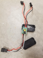
What is this part called and where can I get a replacement?

emjayess

100 µW
Joined
Dec 9, 2022
Messages
8
I need to order this part, but I've exhausted myself searching for it.

This part is inline between the controller and the lights. The three wires that come out of the controller go in and two sets of black/red wires come out and connect to the headlight and tail light wires. I'm not 100% sure, but I believe the white wire is the on/off from the display that opens/closes the circuit to turn the lights on and off.

This is the second of these to blow on this e-bike (I had a spare in a kit I wasn't using before). The voltage before and after this part is 52V when working properly, but it always blows on just the headlight side causing that light to dim (drops to 6v) making the headlight unusable while the tail light stays at 52v. Any insight into that is also appreciated so I don't have to keep replacing them.
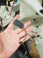
1676861973845.png
1676861997593.png

I did find this photo of a Pedego system with a similar part, but a visit to a Pedego dealer had him stumped as to what it was, which bike it could be from, or whether he could order one. Here's their photo - the part is unidentified and attached to the lights in the upper left of photo:
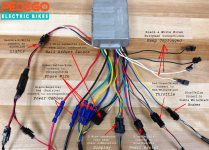
1676862142072.png
 
I might be wrong, but I think it is some kind of relay.
Turns on and off the light basically, this protects the switch so the high voltage doesn't go through the switch and destroys it.

First time I'm seing something like that so I can't help much with sourcing, but I guess if you search for something like "solid state relay ebike" you might have some more luck.
 
I’d check your headlight, since your tail light stays at 52v and your headlight dims. The voltage should be the same at both lights. You’ve already replaced that harness, so that’s probably not the problem.
 
I need to order this part, but I've exhausted myself searching for it.

This part is inline between the controller and the lights. The three wires that come out of the controller go in and two sets of black/red wires come out and connect to the headlight and tail light wires. I'm not 100% sure, but I believe the white wire is the on/off from the display that opens/closes the circuit to turn the lights on and off.
I'd first measure the voltage on the white wire on the controller side, when turning the lighting circuit on and off.

The lower headlight voltage doesn't make senses since both connectors appear to be soldered to the same points on the board, although not completely clear in the pic.
 
With the box unplugged from the bike and the lights, can you use your multimeter to measure the resistance between the red wires for headlight and taillight, and then the black wires for each? If so, please do this both at the board, and at the connector ends of the wires that go to the lights.

It appears to be wired so that you would read zero ohms on each, and if so there should not be a different voltage. If you measure zero at the board but something else at the connectors, one of the crimps at the connector pin or one of the wires to that point might be faulty.

If there is resistance even at the board, then they could be on different switches inside the board (but it doesn't look like there are multiple switches, so that wouldn't make sense), and so one might have failed while the other is still ok.

In that event, since the headlight probably draws more current than the taillight (like the upgraded headlight you used in your first thread here Headlight wire voltage drops from 52V to 6V ) it's probably more than the switch can take so the switch failed.

If so it's very likely that any replacement board designed like this one will fail too, for the same reason.

My advice in that thread is still what I would give now.
 
Amberwolf, as you know from the previous thread, I donated this bike to a disabled/homeless person. I currently don't have it here. He's about 20 miles away, living under a freeway overpass and planning to bring it by in about 7-10 days (I told him it would take that long to find the part).

The first "switch" (what I'm calling it) failed prior to replacing the headlight - when it had a stock Kendo+ (30 LUX) light on it. The bike itself is 6 years old, but had less than 200 miles on it. It's a cadence sensor version of one of my models and was primarily used to show people the difference between the ride quality of a cadence sensor and the bottom bracket torque sensors I use.

I honestly think he's shorting out the lights because he's always "customizing" the bike and moving the light - from fork bridge to a basket, then onto a fairing, and he had even spliced an extension into the wires to make it reach.

The wiring and controller all tested fine, but I replaced the headlight wiring to make sure no exposed wire was contacting the inside of the frame intermittently and to give him more wire length without his splices.

On the switch itself, the red output wires are not soldered in the same spot, but the negative (black) are. This is why one light worked and the other didn't. If you recall, disconnecting the light on the bad output allowed the volts to climb back to 52 without any load, but even a cheap 15 lux light caused the voltage to immediately drop again to 6v.

As far as identifying the part, I'm certified as an e-bike tech by LEVA and I've gone through all of my training manuals and sample schematics and have not seen a single example of using this switch other than in the Pedego photo above. I'm really stumped. I'll reach out to an older Pedego franchise than the one I went to because I suspect it's "old" tech no longer used. *(I only work on my brand and have rarely needed to do any troubleshooting since starting my company 5 years ago. I'm like the guy in the old "lonely Maytag repairman" commercials - just a handful of controllers, a throttle, and a brake sensor in 5 years.

Maybe the best solution would be to bypass the display control and put a separate on/off light switch on the handlebars with an inline fuse to prevent him shorting out the controller during a mod. That would be the quickest and simplest fix I can think of. If you come up with any ideas on what that part is called, let me know!

Thanks to everyone for their answers!
 
Back
Top