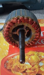
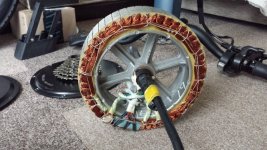
Why never see metal cast around wound stators?

Hummina Shadeeba said:
I think iron will be needed in this motor at least for the great increase in magnetic strength it brings. But the casted zinc? I’ll be seeing what resin I can find that could be vacuumed into the winding first and hopefully not breakdown w the heat of the casting.

650c. Almost heat resilient enough to cast aluminum around
https://www.cotronics.com/vo/cotr/pdf/4703.pdf


Even better possibly
http://www.flexibleceramics.net/high-temp-resin.html


Maybe best to not have any lower temp enamel on the wire which would maybe transform badly with the heat.

Iron does not increase the total amount of magnetic field it just guides the field lines into a more dense higher tesla area it's like focusing a torch the light does not increase yet it has more lumens at it's peak when zoomed.

I've tried to read what your trying to obtain but I'm getting lost, you want more power handling from filling the tooth slot with solid zinc around the copper ?

Why not use a litz wire and fill the tooth properly then back fill with a diamond carbon that's the best performance you will get from a standard motor.

The core can only take so much induction before it saturates around the tooth and forms hot spots that will be your limiting factor any pics of what you are upto ?
 
interesting the core only directs the field produced by coils.

I understood the use of litz wire would be for high frequency. Higher than on a bike or skateboard hub motor. And in the case of a high electrical frequency the main benefit of the litz wire reducing skin effect. I’m instead reading about people rewinding bldc motors taking out the thin multi strand “litz” and replacing with as fat a single strand as possible and getting a lower electrical resistance for the same amount of turns, and that was the goal with no though of eddy currents in the coils.


But please confirm for me the electrical frequency a motor will experience and then we can be on the same page. From memory I think at 30mph with the 84mm wheel and 14 magnets and 12 teeth I hit maybe 10,000erpms. If any frequency would be producing eddy currents or skin effect I’d have thought it would be the pwm frequency but I think that’s smoothened by inductance and that pwm frequency doesn’t occur in the coil and instead just the 10,000 erpm commutation frequency and it not being ac anyway. induction heating happens as low as 5khz. I’ll ride at 30-kHz pwm switching frequency and not turning into an oven any more so than 20khz

But the goal and title of the thread: take a wound motor stator, Vacuum into it a high heat resistant resin that would solidify, then submerg it in a tight fitting cylinder of molten zinc or aluminum, it solidifies, then would have a thermal pathway for the hot copper wires to outside the motor.

High thermally conductive low melt temp alloys with customizable thermal expansion:
https://www.belmontmetals.com/fusible-alloys-low-melting-point/
 
Your question of duty cycle and pwm has made me learn how to calculate a good switching frequency with a vesc.

https://electronics.stackexchange.com/questions/296051/bldc-pwm-frequency

Nice little read by there on calculating duty cycle for efficiency, there's two half's of the puzzle the motor with its inductance and resistance to calculate a time constant and the ideal pwm will have a much shorter time period to keep no load current low then there's the controller mosfets deadtime, switching losses and properly a few things as a novice I've missed.

I know alot less about driving the motor over the basic design principles, I'd love to get a oscilloscope down the line and do some experimenting but at the moment it's out of reach and no area to use it in with little time to use it.

Knowing this means the ironless motors with very little if any inductance will have a very small time constant and then the pwm frequency will have to be alot shorter than that so i suppose they will have an audible frequency used to switch it.

There's also a good bit on the duty cycle and freewheeling alot more research needs to be done in this area by myself.
 
Du. Yea skin effect FROM eddy currents. But if the frequency were high enough to produce substantial Eddys in the windings I think the skin effect would be more of an issue than the losses beside in the zinc due to Eddys

I’d have thought with an ironless motor and low inductance it would need a high switching frequency and there would be less noise. Beyond a switching frequency of 30,000 I don’t hear much

But thanks for the great link with an easy read. I’d really like to get on an oscilloscope myself and see how they work and figure an ideal frequency but the motors I have are all very high inductance (70kv) and I put the switching frequency up to 30,000 just for the noise reduction despite the motor being run fine and more efficiently (i assume in the esc at least) with a much lower frequency.

But if the frequency is chosen right for best efficiency, as in your link, then the coils will not be seeing the pwm frequency and just the commutation frequency which I think would be the erpm on the Vesc decided solely by the pole count and rpm no?
 
I think it's an interesting idea. Are you trying to increase heat conduction from the windings to the inner core of the stator or to the end caps of the motor?

Fwiw, I don't think zinc cast inside the stator core where the windings are will significantly hurt eddy or hysteresis losses. As has been pointed out, the stator iron takes the majority of the flux, so the slots filled with copper and now zinc are subjected to a much weaker field and zinc hysteresis losses should be small since it's non-ferrous???

However, slot area should ideally be filled with as much copper as possible, so I'm not sure how much room there will be for zinc once the windings are potted in their high temp resin.

The end caps idea is interesting since that is a heat path not normally leveraged. It would require larger diameter bearings so that you have static end plates to conduct the heat to the outside. You would have to be careful with eddy losses here because you are putting a conductor outside the slots. Perhaps keeping the magnets a little shorter so that most of their flux goes into the stator would help. Or you could put in some mumetal shields or something... I'm not sure of the heat conductivity of silpad vs zinc, but I'm not sure why silpad tear strength is an issue? It should be mostly under compression right?

Lastly, you've probably tried this already, but why doesn't statorade help you? Because the urethane tire can't get too warm and can't conduct heat? Or is the rpm too high?
 
Getting 100% slot fill is not possible with cyclindrical wire and filling the voids is very doable with cast metal

I’d rather transfer heat to the motor hub or straight out than through the rotor w ferofluid.

I haven’t been able to find anyone who has done this
 
I've had a think about what's going on.

There's two frequencys, the pwm frequency that has a duty cycle to control the amount of voltage the coils see.

Then there's the erpm, the voltage that the motor sees from the pwm signal will spin the motor at a certain rpm that is then calculated by the amount of pole pairs into the erpm of the motor for that given pwm signal.

The smoothing of the pwm signal must only happen at certain frequency as the last post pointed out if there's not enough time constant the no load current will rise and efficiency drop there's an ideal frequency for each motor like a resonance.
 
Ianhill said:
I've had a think about what's going on.

There's two frequencys, the pwm frequency that has a duty cycle to control the amount of voltage the coils see.

Then there's the erpm, the voltage that the motor sees from the pwm signal will spin the motor at a certain rpm that is then calculated by the amount of pole pairs into the erpm of the motor for that given pwm signal.

The smoothing of the pwm signal must only happen at certain frequency as the last post pointed out if there's not enough time constant the no load current will rise and efficiency drop there's an ideal frequency for each motor like a resonance.

I think the pwm fluctuates the voltage the coils will see but ultimately it’s goal is to adjust the current the motor sees to be smooth and consistent and during the on time. I assume that if the motor has enough inductance to keep the current high in the coil during the on period then it doesn’t matter how much faster the pwm frequency and the coils will still see the same current and the motor wouldn’t be adversely effected by a higher frequency but the esc will have losses w the higher switching. I understood that the most efficient pwm would be the lowest that produces a consistent current. If it’s slower than that then there would be torque pulses or other losses or maybe not even run but if faster it wouldn’t make any difference and the coil will receive the same current
 
I came to that conclusion keep the switching frequency low as possible for the mosfets switching efficency but high enough to be well clear of the L/R time constant.

The Torque/current in the motor is self regulating in normal running circumstances the faster it's spun the larger the back emf becomes and it's ability to pass current reduces that's why a stall situation is so bad there's no back emf and no current control other than the esc.

The controller then current controls with shunts monitoring 1 or more phases, the vesc 6 uses individual phase monitoring so it can achieve smooth foc control at start up when there's no rotor position detection until it makes a movement.

Looking at the specific heat capacity of zinc it's a little bit lower than steel as well as it's thermal conductivity so the best way to fill that slot is with copper.

Now the end turns is another thing I've seen potting on these to help complete a thermal path back to the core as they are floating in air even potting compound gives a better thermal path back to the iron, typically it's the end turns that melt when the windings are overloaded with current and it's this area that gets attention on industrial motors.

The statorade is good for heat exchange from the core to the outer case but there needs to be additional fins or a large alloy heat sink available to lose the heat.

I got a dualtron hub 60v1600w this would work great with statorade the outer wheel is alloy and alot of it compared to a push bike hub motor with spokes but the down side is there's no room for fins on the magnet ring, there's only a large bit of alloy for a large dump of heat one time and then a heatsink could be placed on the none disc side that could increase the area of contact to the air to help lose heat on the side cover but it's thermal path is further so it's a one time dump of crazy power and a little higher sustainable overall.

 
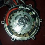
You can see the mild steel wall beside the stator here that i would cast to and through then contacting the black aluminum hanger
Mild steel is maybe half as conductive as zinc. There’s also a bunch of low melt alloys of aluminum and other metals I linked above and I haven’t found their thermal conductivity and the manufacturer doesn’t know them. Copper ofcourse would be great but it’s melt temp is very high at 2000f
https://www.google.com/amp/s/www.engineeringtoolbox.com/amp/thermal-conductivity-metals-d_858.html

With ur motor above it doesn’t seem to have a good thermal path from the stator to the hub to somewhere. The steel axle seems the only outside contact point going that route. It seems a shame to have to go through the rotor and magnets as maybe they are cheap low temp ability magnets and then the motor would have a lower power ability. Often don’t know what temp magnets can get to
 
If you really want to mess around with this stuff, use a low melting point alloy for a first go. 58% bismuth 42% tin doesn't have zinc's conductivity, but it is easy to handle and won't dump destructive amounts of heat all through your motor as it solidifies. Melting point as low as 138C. If you intend to cook your motor at a higher temperature than that, there are lots of other tin alloys with higher MPs, but still much lower than zinc.

I suppose you're going to do this metallic potting before you terminate the windings and install Hall sensors?
 
https://www.elektrisola.com/us/magnet-wire/magnet-wire-types/nema.html

Essex wire has a good graph demonstrating how the wire is temp rated at 20,000 or maybe 40,000 hours use and for shorter periods of time will take higher temp. The link above has a “cut through temperature.”
It’s 752f for the 240c rated wire being conservative. But what’s the most conductive metal or alloy that has a melt temp under 750f? And maybe most important which has a thermal expansion rate most similar to copper?

I won’t put sensors in. Id rather cover a wye bundle in the windings with something heat resistant enough than do delta but delta would eliminate a lot of risk of shorting. But if everything else holds up wouldn’t even need to cover the wye bundle and not ideal with a half-short through the wye but as long as nothing else happens in the future... There unfortunately would be possibly a large decrease in the longevity of the insulation after such a heat shock. At least it would be an oxygen-free environment which could help
 
Electrical conductivity.
Thermal conductivity.
Thermal expansion.
Specific heat value.
Reaction to a magnetic field at both ends of the motors thermal working limits.

Any others anyone can chime in ?

I plan on encapsulating the end turns on the motor pictured and use ferrofluid so I need to consider contact with oil too for this I might go with an off the shelf specific resin I'll do a bit of research first.

On the mxus 3k motor there's an aluminuim spider in the center but on a 6.5 inch motor the stator is to small to accomadate any decent size piece of alloy so going out of my way to destroy the motor and rebuild it would gain me very little unless it's built from factory like it, there's loads of areas small gains could be made from it but in general for it's price of £180 to my door I can't complain.

IMG_20190208_154250451.jpg
_IMG_000000_000000.jpg
 
Those resins if any good are expensive. I think the best thing u could do, and it would be easily stripable if it fails, as apposed to resin, is solder. Or some other metal.

https://www.google.com/amp/s/www.electronics-cooling.com/2006/08/thermal-conductivity-of-solders/amp/


https://www.engineeringtoolbox.com/amp/thermal-conductivity-metals-d_858.html

I’d like to see a cost and thermal conductivity competitor that’s not metal. And the ability to melt down again is great
 
I Think the encapsulants accelarated mass needs to be considered to as well as that extra mass increasing the no load current what a massive juggling act.
 
Hummina Shadeeba said:
No spinning stator so no added spinning mass.

For outrunners and hubs like our own true only total mass is effected but Inrunners like my kuberg motor then it's a consideration.

IMG_20190208_223309767.jpg
 
Ianhill said:
Hummina Shadeeba said:
No spinning stator so no added spinning mass.

For outrunners and hubs like our own true only total mass is effected but Inrunners like my kuberg motor then it's a consideration.

IMG_20190208_223309767.jpg

I'm chatting shit again the coils are stationary so pot,solder away not making much sense today i think I was confused thinking about a dc motors rotor brain fart.
 
Hummina Shadeeba said:
Zeroing in.
http://mobile.indium.com/thermal-interface-materials/solder-tim/
I’ll ask them about using in a motor on Monday.

I thought of indium before, because it's got better thermal and electrical conductivity than solder, it's soft as all get out, and it melts at about 300F.

Unfortunately it's supplied by a cartel and it has a bunch of semiconductor industry applications, so it's extremely expensive.
 
Thermal grizzly cryonaut cpu paste is a mixture of tin, gallium and indium and that stuff eats into the surface of anything that's not nickel plated, putting it on the enamel of the copper is a risk in itself and this stuff is liquid and thin so it maybe highly conductive but only a thin coat can be applied limiting it's ability compared to a generous portion of a solid setting aluminuim doped compound.
 
The tin alloys would be cheap and maybe straight tin would work with a melt temp of 400f, soft, thermal expansion less then indium at least, great thermal transfer. 400f is no problem for the amount of time the coils would be at that temp with the cast metal around it and can use standard 200c wire. gunna see what the indium people say. Surely it’s not that easy and They will say I have to buy their stuff. Humm
 
Hummina Shadeeba said:
If an ac current were being fed through the coils at a fast enough frequency to produce eddy currents the iron teeth would be heating up especially as it’s feromagnetic and would be heating through hysteresis as well as Eddys. But they don’t heat through these and the frequency is not fast enough. Why? I’m thinking while the esc has a switching frequency within the range of an induction heater its just pwm and not true ac and this switching doesn’t get past the inductance of the coils anyway before smoothened. the commutation frequency is still not fast enough but if it were able to be sped up a lot then maybe it would be an induction heater no? . None the less the motor hasn’t shown to be an induction heater thus far and theres no reason to believe this would change with an added 20% material within the slots

Inductor with shorted turn is a transformer or autotransformer depending where the short is. Primary then only presents leakage inductance. Current circulating in the short cancels what would otherwise appear as magnetizing inductance. By adding a short, the full amount of inductance you depend upon to block a switching frequency may not be there anymore.

Could add external inductors of ferrite or other eddy-proof core to your feed lines to block the switching frequency. Then the motor only has to deal with eddies at the turning frequency, which may find the conductive filler not large enough to support a significant eddy.

Of course if the filler makes a complete turn around the core anywhere, its probably a short even at low frequency. If a short can't repel out of the way because of attachment to the stator, that short is going to steal enough opposing current to cancel the field instead. Both the coil and shorted turn are going to heat while doing no useful work.

A shorted rotor that can move out of the way is less a problem, in some cases an advantage. Taken to extreme, the AC induction motor with deliberately shorted rotor gives perfect example. Same for copper banded permanent magnets. But a shorted rotor is also unlikely to move at pwm speeds, so could still misbehave as a shorted secondary at pwm switching frequency. Again, external chokes can solve. Some controllers may already have suitable chokes, for this or RF interference reasons.

Zamac 3 may have the best casting properties if other parts can take the heat, but that assumes other parts also don't expand or shrink.
 
But what short? There’s no short


I’m finding indium easily gotten on Amazon and not tooo expensive but strangely all the indium stores I’ve called haven’t heard of using it in this way and seems Ill have to do it myself to find out
zamac3 I see. There’s a bunch of options it seems with indium maybe the best option, maybe, but with small investment and risk will see what happens.
 
Induim gets doped with iron to make it magnetic for industrial uses so my educated guess is that over time the Induim will become magnetic at least on it's surface, I don't know if you have look at the galvanic corrosion properties but it's the enamel on the winding that will have to form a seal for the copper and Induim from electrical shorting as well as stop induim from galvanic reaction after it's been exposed to high heat, if it's going to work it will be for a limited time I'm afraid drastically shorten the life of the motor.

The solution must be stable enough to apply and not corrode or you will make the motor lose performance through added losses that will have a progressive nature.

Aluminuim powder has little effect even in strong fields and in a potting compound is isolated so any small eddys remain small where as a liquid cast is one piece and going to have less resistance if it's becomes contaimated/oxidize and could become more ferromagmetic inducing more current creating extra heat more losses.

Please excuse my previous post I was wrapped up in work i done a 40 hour day, lifes deadlines creating impossible tasks that must be met and were I'm from failure is not an option.
 
Back
Top