winkinatcha
10 kW
Background
As some may know from reading previous posts by me, I am currently the proud owner of around 30 DD Golden Motor Style hubmotor kits, approximately evenly distributed as front or rear.
I've had these kits for a few months, and was pottering around with them with the intention of basically "value adding" and then on-selling the kits for other DIY e-bikers... trying very much to fill a perceived gap between basic kits ya can buy on the interwebs and through local importers here in Aus, and pre-built e-bikes... IE supplying a comprehensive amount of information about the kits, coupled with experience over a number of builds with said kits so that first timers and less experienced enthusiasts could have a pretty straight forward experience making their own builds. Maybe even along the way I might sell some of my builds, and who knows, might be able to support my hobby and continue learning n building and enjoying the e-bike revolution..
As Luck would have it roughly 1 month ago i was made redundant from my (6 year) job, Documentation writer, primarily IT-based, something which I've been doing for around 20 years as a trade, and as MORE luck would have it being employed in that position in Australia, with a pretty humane company, I received a payout equivalent to approx 6 months salary post tax.
As well as the Recentish IT and city dwlling experience, I've got a fair amount of relevant practical experience (son of an electronics engineer, my teens spent country living in a farming community whilst my family pursued a survivalist existence (read gun-toting hippies, n yes I have eaten many forms of our Australian native wild-life) and a motorcycle and all things quicko and mechanical enthusist with a penchant for getting down n dirty, bush mechanicing and maintaining own vehicles, into alternative energy and blessed with a gift for the gab and a love for my fellow humans... blah blah blah...
What I am currently doing
long story short, I am seeing if I can actually support myself through being part of the e-bike phenomenon, starting with these kits...
with my time to all intents and purposes being 100% MY time at the moment, I've set about seeing what these kits can do, and specifically pursuing A fantasy of converting the kits (through additional components and modifications) into clearly and easily installable items with a simple upgrade path from Aus-legal (250 watts, 25kph top speed pedelec) to 1000 watt 50 kph "strictly for off-road" capable... where off-road basically means the owner has an understanding that above the legal power and speed limitations, it is not legal to ride such a machine on dedicated cycle ways, shared paths, footpaths, or carriageways... but to all intents and purposes, 'tis basically the same components (barring higher voltage/capacity batteries) with a few easily performed modifications to convert a legal kit to a more enjoyable (and in my mind practical) e-bike of 500w Plus.
What I have done so far
In the pursuance of such a goal I have already sussed out the "top-end" ( Power and performance first, restrictions later). Simple Pimple... Just up the voltage using the kit's vanilla form of 24v 20-25 amp controllers with robust wheels to 36v (800 watts, 35kph) and 48 (1000 w). Simple mods for higher voltage of disconnecting the dinky throttle based voltage indicator rated only for 24, and battery related stuff (via BMS, and/pr low voltage warning/indicator to account for LVC of controller being based on 24v and thus not useful for higher voltage battery protection. Done, tested many kilometers in these higher forms, no comment on whether they were ridden off-road 8).
Currently have three working builds, a front-wheel (experimental road oriented build) and two rear wheel builds, one which is a very robust hardtail mountainbike, and the other which is my main prototype based on a brand new entrance level "mountain bike-like" hardtail.
I have three new bikes (cheapy dual suspension, cheapy 700c and cheapy cruiser) three restored middle to hi quality second hand bikes (all 26" MTB style), One Uber awesome Lov-of-my-life 2003 Norco Atomica downhill racing MTB all lined up waiting for conversion.
(I also have a few other currently non-functioning e-bike projects including one mostly dismantled 2kw Hyena kit-based build, one 700c commercial e-bike underseat battery roadish Alloy framed e-bike and one 24v external (non hub drive) 24v granny bike and one 200w upright e-trike)
Plus enough New quality and bog-standard and "sourced from junked bikes" parts to upscale about 10 more bikes... and build another three blah blah blah some more.. Oh and a dedicated though smallish workshop for the bike/e-bike mechanicing, an inside room dedicated to electronics and hardware hacking, and a cat that is somewhat happified by my more prevalent presence since my redundification.
I have a variety of Lipo used in 6, 8 and 12s configurations, but will be getting more, a single Ping 24v 10ah battery plus charger, a headway based 36v battery plus charger and enough slas to sink a fairly large boat with which is not for dedicated e-bikes but for showing people the intense difference between old and new battery tech as well as for battery banks for solar collection, and higher tech charging sources.
"legalizing" the Kits
It has come time to bite the bullet and get a kit in a "legal" form.
Initial vanilla form of kit is 24v 500w. Current goal and task... reduce this to 250w
Getting down n Dirty with the controller internals
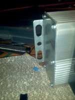
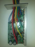
Controllers are 12 FET, with a board marked "www.Tronsung.com"...
And here are some Pics:
Complete Circuit board, component side:
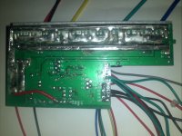
Underside:
Component Side again with a few labels... incomplete:
View attachment 5
Shunt Mods to attenuate power output
Much reading of E/S has me beleiving that a fairly straight forward way of controlling power output is via modifying the existing shunts...
As luck would have it these controllers have two shunts.
thanks to e/s learning i am under the impression that the resistance of these shunts is a fundamental part of what sets the max current and hence max power of a particular controller on a set voltage.
in simple terms, the higher the shunt resistance, the less the current, pretty much linear.
Removal of one of these shunts (using parallel resistance in a DC circuit theory) should Double the resistance and be the simplest method for having a "set" legal 250 watts (half the currrent 500w rated power)
Fortunately or unfortunately, I do not want a simple "remove shunt" solution... for a variety of reasons...
- "upgrading" or returning the controller back to the original 500w spec requires soldering skills.. not a problem for me but not necessarily within the skillset of a new e-bike builder
- Only applicable under 24v battery power, I would like to be able to also offer 36v and 48v at 250w as well for the higher top end speed (and now that I've written that down, I just realised that is silly... higher top end speed will be outside of legal-on-road, so why stuff about at 250w? Well... it would be nice to have a power range anyways... hmmm
So... my first attempt at implimenting shunt mods involved trying to find some kinda "switchable" method for addin or subtracting shunt resistance without having to get the soldering iron out each time to affect a change.
Making the first mods
The idea I first went with is thus...
with the two paralle shunts, I figured they are basically between two rails...
So... my thoughts were, If I disconnected one shunt at one end from one rail, and disconnected the other shunt from one end at the other rail, and extending both rails external to the controller as well as the disconnected ends of the shunts, using either switches or some other kind of manually configurable connections, I should be able to:
connect a single shunt to the opposite rail for half current
Connect disconnected shunt end to disconnected shunt end for 1/4 current
Connect disconnected shunt ends back to rails for Full current.
Implimentation of this went thus.
Opened controller
removed circuit board
disconnected one end of each shunt, one at one rail one at the other
Soldered seperate insulated 10 guage wire to each of disconnected shunt ends
Soldered seperate insulated 10 guage wire to each of the rails using the holes left from disconnecting shunts.
Adjusted and routed wires Outside the controller and connected andersons in such a way that it was impossible to connect rail to rail...
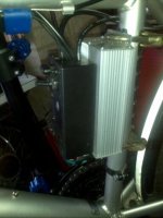
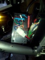
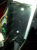
Pics:
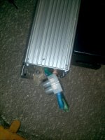
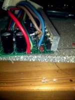
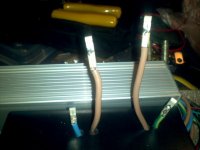
Disconnected shunts re wired... Brown wires to shunt ends, Blue to one rail, Green-yellow to other...
Top view
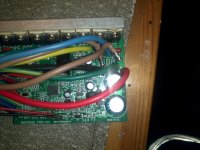
End view:
Rails routed from controller to breakout box and soldered on anderson connectors for manual configuration
... Taking a break to save this will return with more ....
Continued in next post
joe
As some may know from reading previous posts by me, I am currently the proud owner of around 30 DD Golden Motor Style hubmotor kits, approximately evenly distributed as front or rear.
I've had these kits for a few months, and was pottering around with them with the intention of basically "value adding" and then on-selling the kits for other DIY e-bikers... trying very much to fill a perceived gap between basic kits ya can buy on the interwebs and through local importers here in Aus, and pre-built e-bikes... IE supplying a comprehensive amount of information about the kits, coupled with experience over a number of builds with said kits so that first timers and less experienced enthusiasts could have a pretty straight forward experience making their own builds. Maybe even along the way I might sell some of my builds, and who knows, might be able to support my hobby and continue learning n building and enjoying the e-bike revolution..
As Luck would have it roughly 1 month ago i was made redundant from my (6 year) job, Documentation writer, primarily IT-based, something which I've been doing for around 20 years as a trade, and as MORE luck would have it being employed in that position in Australia, with a pretty humane company, I received a payout equivalent to approx 6 months salary post tax.
As well as the Recentish IT and city dwlling experience, I've got a fair amount of relevant practical experience (son of an electronics engineer, my teens spent country living in a farming community whilst my family pursued a survivalist existence (read gun-toting hippies, n yes I have eaten many forms of our Australian native wild-life) and a motorcycle and all things quicko and mechanical enthusist with a penchant for getting down n dirty, bush mechanicing and maintaining own vehicles, into alternative energy and blessed with a gift for the gab and a love for my fellow humans... blah blah blah...
What I am currently doing
long story short, I am seeing if I can actually support myself through being part of the e-bike phenomenon, starting with these kits...
with my time to all intents and purposes being 100% MY time at the moment, I've set about seeing what these kits can do, and specifically pursuing A fantasy of converting the kits (through additional components and modifications) into clearly and easily installable items with a simple upgrade path from Aus-legal (250 watts, 25kph top speed pedelec) to 1000 watt 50 kph "strictly for off-road" capable... where off-road basically means the owner has an understanding that above the legal power and speed limitations, it is not legal to ride such a machine on dedicated cycle ways, shared paths, footpaths, or carriageways... but to all intents and purposes, 'tis basically the same components (barring higher voltage/capacity batteries) with a few easily performed modifications to convert a legal kit to a more enjoyable (and in my mind practical) e-bike of 500w Plus.
What I have done so far
In the pursuance of such a goal I have already sussed out the "top-end" (
Currently have three working builds, a front-wheel (experimental road oriented build) and two rear wheel builds, one which is a very robust hardtail mountainbike, and the other which is my main prototype based on a brand new entrance level "mountain bike-like" hardtail.
I have three new bikes (cheapy dual suspension, cheapy 700c and cheapy cruiser) three restored middle to hi quality second hand bikes (all 26" MTB style), One Uber awesome Lov-of-my-life 2003 Norco Atomica downhill racing MTB all lined up waiting for conversion.
(I also have a few other currently non-functioning e-bike projects including one mostly dismantled 2kw Hyena kit-based build, one 700c commercial e-bike underseat battery roadish Alloy framed e-bike and one 24v external (non hub drive) 24v granny bike and one 200w upright e-trike)
Plus enough New quality and bog-standard and "sourced from junked bikes" parts to upscale about 10 more bikes... and build another three blah blah blah some more.. Oh and a dedicated though smallish workshop for the bike/e-bike mechanicing, an inside room dedicated to electronics and hardware hacking, and a cat that is somewhat happified by my more prevalent presence since my redundification.
I have a variety of Lipo used in 6, 8 and 12s configurations, but will be getting more, a single Ping 24v 10ah battery plus charger, a headway based 36v battery plus charger and enough slas to sink a fairly large boat with which is not for dedicated e-bikes but for showing people the intense difference between old and new battery tech as well as for battery banks for solar collection, and higher tech charging sources.
"legalizing" the Kits
It has come time to bite the bullet and get a kit in a "legal" form.
Initial vanilla form of kit is 24v 500w. Current goal and task... reduce this to 250w
Getting down n Dirty with the controller internals
Controllers are 12 FET, with a board marked "www.Tronsung.com"...
And here are some Pics:
Complete Circuit board, component side:

Underside:

Component Side again with a few labels... incomplete:
View attachment 5
Shunt Mods to attenuate power output
Much reading of E/S has me beleiving that a fairly straight forward way of controlling power output is via modifying the existing shunts...
As luck would have it these controllers have two shunts.
thanks to e/s learning i am under the impression that the resistance of these shunts is a fundamental part of what sets the max current and hence max power of a particular controller on a set voltage.
in simple terms, the higher the shunt resistance, the less the current, pretty much linear.
Removal of one of these shunts (using parallel resistance in a DC circuit theory) should Double the resistance and be the simplest method for having a "set" legal 250 watts (half the currrent 500w rated power)
Fortunately or unfortunately, I do not want a simple "remove shunt" solution... for a variety of reasons...
- "upgrading" or returning the controller back to the original 500w spec requires soldering skills.. not a problem for me but not necessarily within the skillset of a new e-bike builder
- Only applicable under 24v battery power, I would like to be able to also offer 36v and 48v at 250w as well for the higher top end speed (and now that I've written that down, I just realised that is silly... higher top end speed will be outside of legal-on-road, so why stuff about at 250w? Well... it would be nice to have a power range anyways... hmmm
So... my first attempt at implimenting shunt mods involved trying to find some kinda "switchable" method for addin or subtracting shunt resistance without having to get the soldering iron out each time to affect a change.
Making the first mods
The idea I first went with is thus...
with the two paralle shunts, I figured they are basically between two rails...
So... my thoughts were, If I disconnected one shunt at one end from one rail, and disconnected the other shunt from one end at the other rail, and extending both rails external to the controller as well as the disconnected ends of the shunts, using either switches or some other kind of manually configurable connections, I should be able to:
connect a single shunt to the opposite rail for half current
Connect disconnected shunt end to disconnected shunt end for 1/4 current
Connect disconnected shunt ends back to rails for Full current.
Implimentation of this went thus.
Opened controller
removed circuit board
disconnected one end of each shunt, one at one rail one at the other
Soldered seperate insulated 10 guage wire to each of disconnected shunt ends
Soldered seperate insulated 10 guage wire to each of the rails using the holes left from disconnecting shunts.
Adjusted and routed wires Outside the controller and connected andersons in such a way that it was impossible to connect rail to rail...
Pics:
Disconnected shunts re wired... Brown wires to shunt ends, Blue to one rail, Green-yellow to other...
Top view

End view:

Rails routed from controller to breakout box and soldered on anderson connectors for manual configuration

... Taking a break to save this will return with more ....
Continued in next post
joe


