
I think its a square of RPM, I meen eddy current losses are a square of rpm. But its realy hard to get the Iron poweder packed in tight so it will have a lower saturation point causing it to have lower torque but higher hp!Miles said:It only has an efficiency advantage at very high frequencies, though....Arlo1 said:I played with iron powder for a stator and can tell you its amazing!
You are using an out of date browser. It may not display this or other websites correctly.
You should upgrade or use an alternative browser.
You should upgrade or use an alternative browser.
Worlds Worst Dyno - Version 2
- Thread starter adrian_sm
- Start date
adrian_sm
1 MW
Did a bit more testing this time with the SK3-6374-168 at different PWM frequencies and timing advance.
Summary No-load data
Notes:
- As the motor warms up the no-load current tends to drop
- I didn't wait for the current readings to full stabilise, so don't rely on them too much.
Summary Temperature Data
Notes:
- I don't trust some of the predicted equilibrium temps, due to the noise in the sample temp data. Particularly the 8kHz/30-deg
Test Setup Notes:
- 0-10min @ 100% throttle
- 10-20 mins at 50% throttle/speed
- I couldn't be bothered waiting for everything to cool, so starting temperature are not the same.

Preliminary Findings:
- timing affects ESC temperature
- 16kHz PWM & 0-deg timing is still generating high heat in ESC, particularly at lower speeds.
- @ 30 deg timing, loaded speeds were similar to the 6364-190kv at 0 deg timing, but ran coolor. Wow.
- @ 30 deg timing, caused higher motor temps but only by +3deg or so.
- this motor runs cooler than the 6364-190kv for similar torque levels (No big surprise)
Summary No-load data
Notes:
- As the motor warms up the no-load current tends to drop
- I didn't wait for the current readings to full stabilise, so don't rely on them too much.
Code:
PWM	Timing	Volts	Amps	eHz	RPM
8	0	22.2	2.02	460	3943
8	6	22.2	2.02	461	3951
8	12	22.2	2.02	467	4003
8	18	22.2	2.07	473	4054
8	24	22.2	2.3	490	4200
8	30	22.2	2.42	498	4269
16	0	22.2	2.01	461	3951
16	6	22.2	2.02	462	3960
16	12	22.2	2.02	468	4011
16	18	22.2	2.11	474	4063
16	24	22.2	2.3	490	4200
16	30	22.2	2.42	498	4269
Summary Temperature Data
Notes:
- I don't trust some of the predicted equilibrium temps, due to the noise in the sample temp data. Particularly the 8kHz/30-deg
Code:
PWM	Timing	Volts	PWM	Amps	RPM	Torque	Ambient	M Tfinal	E Tfinal	M dT	E dT	M Eq dT	E Eq dT
16	30	22.2	50	14.8	1934	1.34	25.4	80.1	66.4	54.7	41	55	44.2
8	30	22.2	50	14.56	1968	1.34	25.4	80.3	63.3	54.9	37.9	60	42
8	0	22.2	50	13.43	1819	1.24	25.4	77.4	58.6	52	33.2	53.5	36.3
16	0	22.2	50	13.22	1783	1.2	25.4	78.7	64.8	53.3	39.4	55	44.7
Test Setup Notes:
- 0-10min @ 100% throttle
- 10-20 mins at 50% throttle/speed
- I couldn't be bothered waiting for everything to cool, so starting temperature are not the same.
Preliminary Findings:
- timing affects ESC temperature
- 16kHz PWM & 0-deg timing is still generating high heat in ESC, particularly at lower speeds.
- @ 30 deg timing, loaded speeds were similar to the 6364-190kv at 0 deg timing, but ran coolor. Wow.
- @ 30 deg timing, caused higher motor temps but only by +3deg or so.
- this motor runs cooler than the 6364-190kv for similar torque levels (No big surprise)
adrian_sm
1 MW
In the results above I didn't include efficiency results because I don't trust my method of calculating them. More specifically my torque measurements get an offset due to the way I am zeroing the sensor.
Here is a little video that does a walk through of the Dyno, and explains the torque sensor zero issue.
My plan (I think) is to zero it with out the torque arm in contact, then determine if I need to add an offset to account for the average preload on the sensor. This is complicated by the cogging torque of the motors. So I will need to index the motor around and measure the load cell reading, average it, use that as my offset.
[youtube]PoRFHpq49ks[/youtube]
hillzofvalp
100 kW
I don't know how much help this would be for you.. but I watched your video and thought of this sensor I used recently:
http://www.interlinkelectronics.com/products.php
http://www.interlinkelectronics.com/products.php
If you detached the arm from the load motor and supported it on a knife edge instead, you could weigh the force it applies statically. Once you know that, you could make a small weight that applies the same force. Lift the arm and use the weight to zero the scale, then place the arm back.
I think the zero error will be normally small compared to the actual measurement.
I think the zero error will be normally small compared to the actual measurement.
adrian_sm
1 MW
Motor: SK3-6374-168kv
ESC: YEP 150A
0-10min 100% throttle
10-20min 50% thottle/speed
I couldn't be bothered waiting between test runs for things to cool, so start temperatures are not the same, but calculations were made to predct the thermal equilibrium temperatures.


Temp data was fitted to predict the stabilsed thermal temperature.
Temp data for the motor had 1-2deg accuracy, due to Ir thermometer method of measurement not being repeatable
Motor temperatures taken past moving bell end, at motor widings.
The temp error plus extrapolation makes the motor temperature prediction less accurate.
The following graph use the predicted thermal equilibrium temperatures.


ESC: YEP 150A
Code:
PWM	Timing	Volts	PWM %	Amps	RPM	Torque	Ambient	M Tfinal	E Tfinal	M dT	E dT	M Eq dT	E Eq dT
8	0	22.2	50	13.43	1819	1.24	25.4	77.4	58.6	52	33.2	53.5	36.3
8	6	22.2	50	13.1	1809	1.25	22.6	77.7	57	55.1	34.4	56	38.5
8	12	22.2	50	13.32	1817	1.27	23.7	77.4	57	53.7	33.3	54.8	36.9
8	18	22.2	50	13.04	1873	1.21	27.1	79.3	61.5	52.2	34.4	52.9	38.4
8	24	22.2	50	13.68	1911	1.24	28.1	83.4	64.8	55.3	36.7	55.8	39
8	30	22.2	50	14.56	1968	1.34	25.4	80.3	63.3	54.9	37.9	60	42
16	0	22.2	50	13.22	1783	1.2	25.4	78.7	64.8	53.3	39.4	55	44.7
16	6	22.2	50	12.94	1783	1.25	22.5	74.6	61.2	52.1	38.7	59.4	45.5
16	12	22.2	50	12.89	1791	1.25	24.7	77.8	62.8	53.1	38.1	54.3	41.9
16	18	22.2	50	13.16	1860	1.24	27.1	76.9	63	49.8	35.9	50.3	40.2
16	24	22.2	50	12.98	1920	1.19	28.6	79.3	65.6	50.7	37	50	40.3
16	30	22.2	50	14.8	1934	1.34	25.4	80.1	66.4	54.7	41	55	44.2
8	0	22.2	100	23.5	3571	1.17	25.4	69.9	45.9	44.5	20.5	47	20.6
8	6	22.2	100	23.26	3591	1.19	22.6	68.4	44.1	45.8	21.5	48	26
8	12	22.2	100	24.1	3635	1.22	23.7	70.5	45.3	46.8	21.6	49.6	22.9
8	18	22.2	100	24.1	3687	1.2	27.1	73	48.4	45.9	21.3	47.1	21.6
8	24	22.2	100	25.25	3799	1.21	28.1	77.5	54.6	49.4	26.5	51.7	27.1
8	30	22.2	100	25.82	3842	1.28	25.4	75	53.7	49.6	28.3	50.8	30
16	0	22.2	100	23.24	3578	1.12	25.4	67	45	41.6	19.6	42.9	21.4
16	6	22.2	100	23.98	3571	1.23	22.5	61.9	40.7	39.4	18.2	44.1	21.5
16	12	22.2	100	24.12	3638	1.22	24.7	70.2	45	45.5	20.3	48.3	23.2
16	18	22.2	100	24.71	3676	1.235	27.1	68.4	45.8	41.3	18.7	46.4	21.7
16	24	22.2	100	24.72	3809	1.18	28.6	76.1	53.1	47.5	24.5	48.6	26
16	30	22.2	100	26.5	3825	1.27	25.4	73.7	53.9	48.3	28.5	52.5	33.5
0-10min 100% throttle
10-20min 50% thottle/speed
I couldn't be bothered waiting between test runs for things to cool, so start temperatures are not the same, but calculations were made to predct the thermal equilibrium temperatures.
Temp data was fitted to predict the stabilsed thermal temperature.
Temp data for the motor had 1-2deg accuracy, due to Ir thermometer method of measurement not being repeatable
Motor temperatures taken past moving bell end, at motor widings.
The temp error plus extrapolation makes the motor temperature prediction less accurate.
The following graph use the predicted thermal equilibrium temperatures.
adrian_sm
1 MW
Speed versus timing advance for no load, and ~1.2N.m.

adrian_sm
1 MW
Observations:
- Motor heat is the most critical thermal issue with this system
- Motor heat is more critical at partial throttle or less than full speed conditions, even at the same torque output
- increasing timing advance can increase the motor speed by up to 8%, under both loaded an unloaded conditions
- increasing timing advance increases motor temperature at full throttle by 5-10 deg-C
- increasing timing advance above 12 deg may have a positive effect at 16kHz PWM in lowering motor temperatures.
- higher PWM frequencies increase ESC temperature at partial throttle conditions, by up to 18 deg-C @ 0 deg timing
- increasing the timing lessens the heating difference between low and high PWM ESC heating.
Conclusions (for the load conditions tested):
- not net advantage to increasing timing above 18deg
- potentially some advantage to running 16kHz PWM and 18 deg timing
--- possibly lower motor temperature atcritical partial throttle/lower speed, at expense of slightly high temp at full throttle/ full speed
--- ~3% high motor speed
--- lower motor noise ( at potentially annoying high frequency)
Summary:
I am going to give 16kHz and 18 deg a go for more testing.
adrian_sm
1 MW
Trying to declutter the Motor temp graph.
Here is just the 16kHz curves.
Here is just the 16kHz curves.
adrian_sm
1 MW
fechter said:If you detached the arm from the load motor and supported it on a knife edge instead, you could weigh the force it applies statically. Once you know that, you could make a small weight that applies the same force. Lift the arm and use the weight to zero the scale, then place the arm back.
I think the zero error will be normally small compared to the actual measurement.
I see what you are getting at. But it is not just the weight of the arm, but also the phase wires, and the cogging torque that are the issue. So as soon as I rotate the arm (screw mounted to the generators stator) slightly the load in it varies. If I move the rotor then it varies again.
I ended up just zeroing it without the arm in contact with the scales. This may introduce a small
offset in the order of 2-4% at the torque levels I am working at, but this should give me the most repeatable results.
adrian_sm
1 MW
Arrrgghhh. Damn.
I blew up my new favourite controller, the YEP 150A.
I rapidly reduced the throttle, then suddenly power supply fuse tripped, and nothing. Cycled the power supply nothing. Disconnected the ESC, and powered up the power supply, fine. ESC dead.
I have noticed that even though I had the brake and governer settings Off, it was still slowing down the motor when I reduce the throttle too quickly.
Tried powering the ESC up via a 2s LiPo pack and poof, actually saw the magic smoke release this time, from somewhere in between the two FET boards, close to the phase wire end.
My guess a shoot through FET failure.
I hate it when that happens. 
Does that controller have synchronous rectification? If so, it will inherently have a braking effect when the throttle is reduced quickly.
Does that controller have synchronous rectification? If so, it will inherently have a braking effect when the throttle is reduced quickly.
adrian_sm
1 MW
Yep. That is why I like the ESC so much. But I thought by turning off the brake setting they may have had some smarts to change the braking behavior when the throttle input drops rapidly.
Makes you wonder what the brake settings are for. 
I used to have a controller with synchronous rectification on my old Zappy scooter. If I slammed the throttle off, it would try to lock up the rear wheel and almost throw me off. In practice, the drive belt would skip when regen got too high. I finally made a regen current limiter for it that kept motor current at a safe level when the throttle was suddenly dropped. This worked great but would be very hard to do on a RC setup.
If it had a slower throttle ramp speed, it would greatly reduce the peak current. They make speed adjusters for RC servos.
adrian_sm
1 MW
Thanks for the input. It is not an issue for how I intend to put it into service, as I will fully control the ramp up and down speeds. Just an issue to be aware of for anyone wanting to use these ESCs raw.
And your right those RC servo speed adjusters do work surprisingly well.
And your right those RC servo speed adjusters do work surprisingly well.
adrian_sm said:I blew up my new favourite controller, the YEP 150A.
I rapidly reduced the throttle, then suddenly power supply fuse tripped, and nothing. Cycled the power supply nothing. Disconnected the ESC, and powered up the power supply, fine. ESC dead.
I have noticed that even though I had the brake and governer settings Off, it was still slowing down the motor when I reduce the throttle too quickly.
Tried powering the ESC up via a 2s LiPo pack and poof, actually saw the magic smoke release this time, from somewhere in between the two FET boards, close to the phase wire end.
My guess a shoot through FET failure.
Sound's like an over voltage caused by the current inversion when reducing the throttle. This is one of the challenges from the synchronous rectification, the current can flow in both direction and this need to be managed carefully by either monitoring the phase current and/or the capacitor voltage relatively quickly. My 1st controller didn't have phase current monitoring and would regularly trip the power supply when reducing the throttle because of current inversion. This is less of an issue when connected to the battery which can take in the current.
adrian_sm
1 MW
Just to be clear.... I am not sure if it relavent but my setup is:
Power supply -> drive ESC + regen controller, via a 1:2 parallel type adapter.
So any regen during normal testing reduces the load on the power supply.
But I guess when I went 100-0% throttle both controllers are trying to generate current, and shove that back at the power supply.... Hmmm not good. Voltage increases.... FET dies.
I guess the good news out of this story is under normal conditions hooked up to a battery, then it will take the current and not have the voltage go crazy.
Not sure if I am confident enough to put that theory to the test when I get a replacement controller (which is on back order) from hobby king.
Might chase one of the other suppliers down.
adrian_sm
1 MW
Thanks Arlo. Pity the lure of dirt bike riding with a mate is too strong. :lol:
News:
- Hobbyking were out of stoke of the YEP 150A

- But luckily I found another supplier, HiModel. They appear to be the manufacturers. Anyway 5 days after ordering I have a couple in my hands. Price is pretty much identical, and the Hobbyking programming card appears to work for both.
Testing:
Here are the test results of running SK3-6374-168kV at full throttle, with different loads.
Most of the data is at 16.6V, with some data points at 22.2V.
The graph plots torque on the horizontal axis.
And the predicted equilibrium temperature above ambient in degrees Celcius. Again these measurements are taken while the motor is spinning, so is less than the actual winding temperatures.
Based on this, and extrapolating the data with a quadratic function, looks like the max sustainable torque would only be around 2.0 N.m.

Now I want to:
- repeat this at the higher voltage, to see how speed affects the sustainable torque.
- different voltage @ partial throttle, aiming for the same RPM/torque as the 16.6V data points. To see how PWM chopping the current affects motor temp, and sustainable torque.
News:
- Hobbyking were out of stoke of the YEP 150A
- But luckily I found another supplier, HiModel. They appear to be the manufacturers. Anyway 5 days after ordering I have a couple in my hands. Price is pretty much identical, and the Hobbyking programming card appears to work for both.
Testing:
Here are the test results of running SK3-6374-168kV at full throttle, with different loads.
Most of the data is at 16.6V, with some data points at 22.2V.
The graph plots torque on the horizontal axis.
And the predicted equilibrium temperature above ambient in degrees Celcius. Again these measurements are taken while the motor is spinning, so is less than the actual winding temperatures.
Based on this, and extrapolating the data with a quadratic function, looks like the max sustainable torque would only be around 2.0 N.m.
Now I want to:
- repeat this at the higher voltage, to see how speed affects the sustainable torque.
- different voltage @ partial throttle, aiming for the same RPM/torque as the 16.6V data points. To see how PWM chopping the current affects motor temp, and sustainable torque.
adrian_sm
1 MW
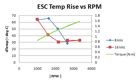
Synchronous Rectification + High PWM rate = GOOD
Check out the temperature rise for the ESC under the same load conditions, but at different PWM rates. 8 vs 16 kHz.
16 kHz is a hands down winner at the lower speeds.
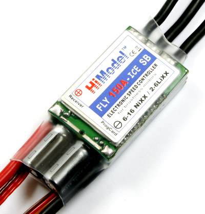
ESC: HiModel 150Amp ICE
- 18 deg timing
- synchronous rectification = ON
Horizontal axis is RPM.
Green lines shows the torque load [N.m] applied by my light bulb load bank
Blue line is the 8kHz PWM
Red line is the 16kHz
The temperatures are the predicted equilibrium temp above ambient, based on ~12 min of constant load, then extrapolation.

Observations:
- the higher PWM rate is keeping the phase currents in check since the inductance is doing a lazy job of it once the BEMF drops off.
- due to the synchronous rectification the switching losses are not that bad, so the higher switching frequency does not lead to a lot of extra waste heat on its own.
Check out the temperature rise for the ESC under the same load conditions, but at different PWM rates. 8 vs 16 kHz.
16 kHz is a hands down winner at the lower speeds.
ESC: HiModel 150Amp ICE
- 18 deg timing
- synchronous rectification = ON
Horizontal axis is RPM.
Green lines shows the torque load [N.m] applied by my light bulb load bank
Blue line is the 8kHz PWM
Red line is the 16kHz
The temperatures are the predicted equilibrium temp above ambient, based on ~12 min of constant load, then extrapolation.
Observations:
- the higher PWM rate is keeping the phase currents in check since the inductance is doing a lazy job of it once the BEMF drops off.
- due to the synchronous rectification the switching losses are not that bad, so the higher switching frequency does not lead to a lot of extra waste heat on its own.
adrian_sm
1 MW
Oh and the motor temp didn't really care about PWM frequency (relatively speaking)
adrian_sm
1 MW
Dyno Update:
I am now using the cycle analyst speed sensor to measure dyno RPM, this required:
- removing capacitor C6 on the CA PCB to increase the frequency it can measure (as specified in the manual)
- entering the correct pole count = 14
- entering the wheel size = 1667mm, this means the kph reading is actually RPM /10
- mounting the sensor close to the load rotor
adrian_sm
1 MW
adrian_sm said:Synchronous Rectification + High PWM rate = GOOD
Check out the temperature rise for the ESC under the same load conditions, but at different PWM rates. 8 vs 16 kHz.
16 kHz is a hands down winner at the lower speeds.
ESC: HiModel 150Amp ICE
- 18 deg timing
- synchronous rectification = ON
Horizontal axis is RPM.
Green lines shows the torque load [N.m] applied by my light bulb load bank
Blue line is the 8kHz PWM
Red line is the 16kHz
The temperatures are the predicted equilibrium temp above ambient, based on ~12 min of constant load, then extrapolation.
Observations:
- the higher PWM rate is keeping the phase currents in check since the inductance is doing a lazy job of it once the BEMF drops off.
- due to the synchronous rectification the switching losses are not that bad, so the higher switching frequency does not lead to a lot of extra waste heat on its own.
After a discussion over here, I thought I better check that the timing was not the cause of the high ESC heat at low RPM
But after running the same load scenario for 0, 6, & 18 deg timing advance @ ~1000rm and 0.86-0.89 N.m of load, the equilibrium temperature were all between 63 & 66 deg-C. Which is within the noise of my measurement accuracy. So..... I am just blaming low BEMF, low inductance, no active phase current measurement/control, and too slow PWM to keep phase current in check.
adrian_sm
1 MW
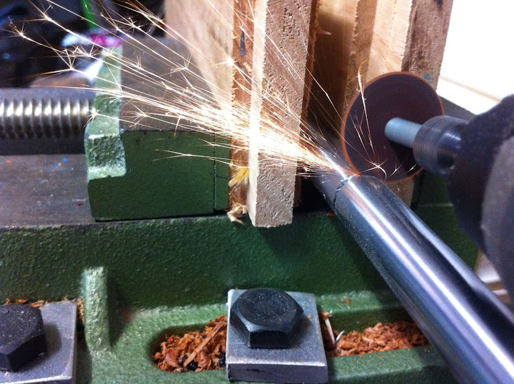
I don't have a lathe but needed to cut a circlip groove in a hardened 12mm shaft. So I adapted my dyno to do the job, along with a dremel.
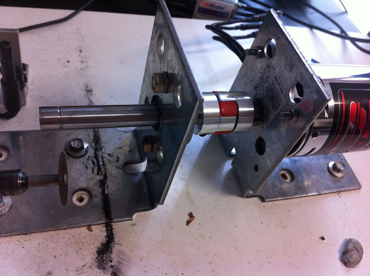
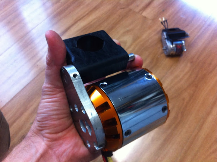
This let me install a shorter shaft in the 8085-250kv mtor, to make a monster friction drive.
And this has nothing to do with the dyno, but I still like the shot I took while cutting the shaft shorter.
This let me install a shorter shaft in the 8085-250kv mtor, to make a monster friction drive.
And this has nothing to do with the dyno, but I still like the shot I took while cutting the shaft shorter.
Similar threads
- Replies
- 15
- Views
- 5,190
- Replies
- 1
- Views
- 393
- Replies
- 35
- Views
- 8,105