
You are using an out of date browser. It may not display this or other websites correctly.
You should upgrade or use an alternative browser.
You should upgrade or use an alternative browser.
Zero-Draw, Solid State Contactor w/Precharge (Arduino)
- Thread starter methods
- Start date
methods
1 GW
fechter said:Hmm.... one more thought:
If the unit is bidirectional and stays connected to the pack to allow HVC cutoff, then doesn't this mean the charger has to be connected to the controller during charging (unless you unplug every time)?
Yes - that is a weakness. I too do not like the idea of having a powered on controller. I need to think that aspect through a bit. I certainly would not advocate disconnecting the controller. Hmm... you have brought up a very good point.
There is something to be said for keeping the charge and discharge paths separate. With separate paths, the heating will be cut in half and the controller does not need to be powered during charging. You typically don't need as much silicon in the charge path as well.
Tell me about it. :x
The original design had 4pcs of IRFB4115 in the discharge path and 2pcs of IRFB4115 in the charge path. Of course it totally sucks to have to use more mosfets than needed... and to suffer double the heating loss... and I struggled with this for a long time. What finally changed my mind is this:
IF one were to only use one bank of fets in the discharge bath
AND the circuit somehow tripped during operation of the bike
AND the bike started to regenerate current at a high rate
THEN that high rate regen current would pass through the body diode of the fets which could over-charge the pack (not likely) or (more likely) it could over-heat and blow the mosfets.
Yea - so basically unexpected currents running through the body diodes is what finally convinced me to just solve it the most simple way possible.
Damn details...
Damn details is right... I totally appreciate your help on this
-methods
P.S. Doing dual paths also greatly complicates the build of the unit. I may go back and revisit that option - but it is messing... very, very, messy.
methods
1 GW
I agree that if this were an OEM project the way to do it would be to implement a proper pre-charge circuit.
Since I am trying to make more of a general solution - that is as simple as possible - that does not bring in Battery (+) - that has as few failure modes as possible... I am going to roll the dice and see what I can come up with by just PWM'ing right up the main line.
I understand (as you pointed out off line) that hitting the controller input caps with PWM will be hard on them (unsustainable in the case of current limiting) but for short periods of time I think it is going to be OK. IF I keep the pulses of current fast enough I think we can leverage the tiny inductance in the wiring.
For Ebike controllers I am positive that it is going to work.
For Sevcon controllers... we may need to leverage some of the control circuitry onboard with those controllers.
-methods
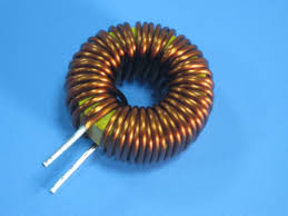
liveforphysics said:However, I think the pre-charge circuit should be one that just drives a pre-set pre-charge algorithm through one of these little guys, starting out at like 1% duty cycle switching at like 20khz across one of these, and then transition to 99% duty cycle over the course of like 2-3seconds, and then close the FETs on hard.
Inductors. They seriously rock for being a part of a pre-charge circuit.
methods
1 GW
Today I was going to post up the two design variants.
One has the FR4 between the two copper plates, mosfets on the outside, then a fastener comes in, through an insulating ring, through a fet, through a bar, through the FR4, through the other bar, through another fet, through an insulating sleeve, then gets a nut. That would be 4 fasteners to hold together an 8 fet unit. The legs would bend 90 degrees and go into the FR4 where the gate resistors and zener diodes would be located right at the pins. The Sources would all get tied together there with a little bit of heat sinking. Then we have a "module"
We could extend that board down and put the rest of the circuitry on it - or have it mate to another board with the smarts.
That is what I have been turning in my mind.
The other idea is to have a different insulating material between the bars and to have all the fets mount vertically (straight legs) into a PCB that has the other electronics.
BUT....
Fechter caught me with my pants down on that controller issue.
Since I was advocating that the controller would not need a power switch - and those with a power switch could just leave it on - this means that if I want to charge then the bike would be "live" and this is not acceptable.
Damn :x
I really, really, really want to keep this simple and clean and general. I can see 100 ways to make this super ebike specific.... but I dont want to do that. I will think a hole through it and figure it out. Thanks for bringing that up Fechter. Seems every time I decide to design something you catch some super pertinent detail that I miss. :wink:
-methods
methods
1 GW
So I guess one option that is totally obvious is that I could provide a simple second low power / high voltage switching fet. Like a 400V 5A fet. This could be used to switch the controller regulator pin or anything else like that. It adds a thousand things that can go wrong....
Or... I could re-investigate a two path solution
In my mind tho - what I see is a single simple solid state relay with no frigging wires or mess or complication. Just install it anywhere - high side, low side, whatever. No polarity. Just plug in the switch. Just plug in active low 5V signal to control it. BAM. Done. Simple. Clean.
As soon as we start bringing that nasty V(+) line in... or as soon as we make a charge path and a discharge path.... or as soon as we start to get ebike specific by switching the LV regualtor on and off... things get complicated and application specific. Now it needs instructions and diagrams and folks who are interested in using it for other things get put off.
Arg.
Simple
Simple simple simple
That is what I want to make - a tool. Something that can be used as a simple tool. The "hammer" in the tool box that you just grab and use... not that tool that requires you to go back and read the directions after 7 years of owning and using.
-methods
methods
1 GW
Ok - just because I dont want to... I am going to sit down and design a variant that has:
* The main simple in and out bars
* Then a small 12G wire for charger
* Then a small pair of 16G wires for Controller regulator control
The complicated and complex solution.
I guess I could design it with connectors - so that someone who just wants to use it "simple" can do so and someone who wants to get all complicated can. It may only be a few more parts - I will post up my best idea in a few.
-methods
johnrobholmes
10 MW
Why couldn't a charge plug be inserted on the pack side of the SSR? When the SSR is turned off there is no power to the controller, no matter if things are being charged or not. I think 99.9% of people are OK with batteries having a power plug and a charge plug. Are you trying to use the SSR to regulate charging as well?
methods
1 GW
So - if I move away from two mosfets in series to a design with a charge channel and a discharge channel - here are some of the pros and cons
PRO:
* 1/2 waste heat on the discharge channel. This means we can instantly double the current rating of the switch
* Now the charge and discharge paths can be controlled separately... so the bike can be "turned off" (via my main power switch) and the charge current can still be allowed to flow (until an HVC event).
* Charge can now be done with the bike in a safe condition
* The main discharge fets and the charger fets will still land on the two main copper terminals (battery and load). This means no external heat sink, no trying to heat sink to the PCB, etc.
CON:
* The switch now has polarity - it only works in one direction - and in the other direction there is always a diode path... i.e. current can flow from the controller to the battery via the power mosfet body diodes.
* The switch now has to be mounted on the low side (ground). This means that the Battery positive terminal, Controller positive, and charger positive will all be common and tied together. The respective grounds will triangulate into this switch.
* The unit can be hooked up wrong/backwards/in the wrong spot
* We now have a third terminal sticking out - which I dont really want to cut a copper bar for - so it will probably be a hole in a PCB, short pigtail of 10AWG, or something like that. Messy messy :? The bar going to the battery and the bar going to the controller will be identical - so it is possible I could use a third identical bar... but really the charge current is a fraction of discharge current and it can easily be passed over a very wide and soldered PCB Trace.
* Battery power can now flow backwards through the charger mosfet into the charger (in the case where the charger fails)
* Now the main switch must switch something besides main power... for we must keep the charge port open which requires keeping the controller powered. This means there will be no "deep sleep" mode that can totally power down the unit - so this means we need a significantly larger battery or a significantly lower average power draw. This is fine... as I was considering this anyway for deep storage datalogging etc.
(((((((((((((((((((((((
That is just a few off the top of my head.
I guess the unit would still totally meet my personal requirements - in fact - it would be better - since what I am making is a 4S Lipo hard pack Car Jump Starter It is way better to have just 4 mosfets in the discharge path instead of 8.
-methods
PRO:
* 1/2 waste heat on the discharge channel. This means we can instantly double the current rating of the switch
* Now the charge and discharge paths can be controlled separately... so the bike can be "turned off" (via my main power switch) and the charge current can still be allowed to flow (until an HVC event).
* Charge can now be done with the bike in a safe condition
* The main discharge fets and the charger fets will still land on the two main copper terminals (battery and load). This means no external heat sink, no trying to heat sink to the PCB, etc.
CON:
* The switch now has polarity - it only works in one direction - and in the other direction there is always a diode path... i.e. current can flow from the controller to the battery via the power mosfet body diodes.
* The switch now has to be mounted on the low side (ground). This means that the Battery positive terminal, Controller positive, and charger positive will all be common and tied together. The respective grounds will triangulate into this switch.
* The unit can be hooked up wrong/backwards/in the wrong spot
* We now have a third terminal sticking out - which I dont really want to cut a copper bar for - so it will probably be a hole in a PCB, short pigtail of 10AWG, or something like that. Messy messy :? The bar going to the battery and the bar going to the controller will be identical - so it is possible I could use a third identical bar... but really the charge current is a fraction of discharge current and it can easily be passed over a very wide and soldered PCB Trace.
* Battery power can now flow backwards through the charger mosfet into the charger (in the case where the charger fails)
* Now the main switch must switch something besides main power... for we must keep the charge port open which requires keeping the controller powered. This means there will be no "deep sleep" mode that can totally power down the unit - so this means we need a significantly larger battery or a significantly lower average power draw. This is fine... as I was considering this anyway for deep storage datalogging etc.
(((((((((((((((((((((((
That is just a few off the top of my head.
I guess the unit would still totally meet my personal requirements - in fact - it would be better - since what I am making is a 4S Lipo hard pack Car Jump Starter
-methods
methods
1 GW
johnrobholmes said:Why couldn't a charge plug be inserted on the pack side of the SSR? When the SSR is turned off there is no power to the controller, no matter if things are being charged or not. I think 99.9% of people are OK with batteries having a power plug and a charge plug. Are you trying to use the SSR to regulate charging as well?
Yes - the whole idea is to replace my HVC Breaker... which terminates charge current if any cell goes over 4.25V
If all we want is LVC to terminate discharge then just using detectors and squelching the throttle - or blowing a fet to turn off the ACC line would work fine - no need for power electronics.
On that note... I could make a simplified model that is bi-directional and connects between the battery & charger & controller ACC line (similar to what Circuit was suggesting). On LVC it could turn off the controller, on HVC it could turn off charge current, and on switch-throw it could just turn off the controller.
-methods
methods
1 GW
I suppose that if I totally back up... and go against what I wanted to do... I could very easily make an ebike specific version of this switch that operates on the controller "switch" line instead of the controller main power line.
I could just use two surface mount IRFB4115 fets for the charge current soldered direction to a PCB board
I could use one single (cheap) 150V mosfet soldered to a PCB board to control the controller power line
Everything else would look the same
We would lose the ability to pre-charge... but we would also offload that issue to a different component.
We would move from the low side to the high side - since switching the controller power line is a lot easier on the high side.
I could totally make a low cost product that would work in this way.
I suppose that if for the "second" mosfet - the one that controls the controller "switch" line was an IRFB4115 I could still use the circuit to control my low power 4S packs as I originally wanted to. My Car Jump Starters will just have to wait
This eliminates all the machining needed since no high power will be flowing... so no big copper bars... so basically it will just look like a Chinese BMS with terminal holes on the ends and beefed up copper traces.
Many that sure would be easy....
This is why I usually design in a vacuum and just put what I have up for sale later. As soon as differing viewpoints start to flow in one can get caught in a quagmire of endless indecision. An idea that excites me (regardless of its feasibility or profitability) gets replaced with an idea that totally gets the job done but is not interesting in any way.
For PreCharge I guess we could make up a set of "Precharge connectors" - which is what I use here. Just a double ended connector with a resistor in it. I turn the controller off, plug in this resistor for a few seconds, then remove it, plug in the main power wires, then turn on controller. It can be done a dozen more clever ways but really it is not needed. I really dont like the idea of folks taking their bike apart... best to just never do it unless you have to.
Going this route will also make us a lot more compatible with Lyen type controllers that dont have a power switch and already have wires coming out. Ebikes.ca owners will have to open the side cover and cut a wire (barf). Or maybe we can tap-in at the CA plug - make a male/female inline plug that taps us in :wink:
Arg... totally off track
-methods
methods
1 GW
Ok - here is a different idea:
Say I make 2 different kinds of modules... one high power and one low power
Module 1 would look exactly like I described in the original post. It could serve as an all-in-one solution *if* the user wants to have a second switch to turn the controller power off manually for charging.
Module 2 would be a lower power version - just a PCB board with board mount fets. It would have only two connections - so a single (low cost) module could control the charge current. A second low cost and identical module could control the controller "switch" line.
In this way a person could choose to buy one, large, high power SSR.... or they could choose to do it with modules.
For the module solution a user would simply wire one between their existing charge plug and their charger. No switch needed there - only an attachment to the BMS. A second and independent module would or could be attached between the charger "switch" line and battery (+)... effectively replacing the manual switch on the controller. This unit could be switched via the handlebars to turn the controller on and off while still being able to cut almost all power for an LVC event
A third user may choose to take a high power module to cut all the power to their controller and a second low power module just to cut charge current (though you would not need it)
I could then use the lower power modules for my 4S accessory packs (Say... 20A or 50A). Then I could use the higher power SSR for my jump starter.
I should probably draw up a picture or two for those who dont read the text")

-methods
Say I make 2 different kinds of modules... one high power and one low power
Module 1 would look exactly like I described in the original post. It could serve as an all-in-one solution *if* the user wants to have a second switch to turn the controller power off manually for charging.
Module 2 would be a lower power version - just a PCB board with board mount fets. It would have only two connections - so a single (low cost) module could control the charge current. A second low cost and identical module could control the controller "switch" line.
In this way a person could choose to buy one, large, high power SSR.... or they could choose to do it with modules.
For the module solution a user would simply wire one between their existing charge plug and their charger. No switch needed there - only an attachment to the BMS. A second and independent module would or could be attached between the charger "switch" line and battery (+)... effectively replacing the manual switch on the controller. This unit could be switched via the handlebars to turn the controller on and off while still being able to cut almost all power for an LVC event
A third user may choose to take a high power module to cut all the power to their controller and a second low power module just to cut charge current (though you would not need it)
I could then use the lower power modules for my 4S accessory packs (Say... 20A or 50A). Then I could use the higher power SSR for my jump starter.
I should probably draw up a picture or two for those who dont read the text
-methods
methods
1 GW
P.S. Combining the charge power cut with the controller "switch" cut in the same circuit does not work well - since common would end up being V(+) - it makes for a driver mess. Ugly. Better to just keep it simple.
Simple
Simple is what people like. If it is not simple then they buy it and it sits on a shelf... I know because I get emails some times from people who bought things 2 years ago and now are just hooking them up. I know because I hate writing documentation
I am going to draw a picture. Mostly boobs and stuff - but a simple PCB implementation as well.
-methods
methods said:I am going to draw a picture. Mostly boobs and stuff - but a simple PCB implementation as well.
-methods
I should put that in my facebook status. :lol:
methods
1 GW
Damn - I forgot to include the boobs in the corner
Next picture. Maybe some more graphic stuff too.... Fechter likes the top shelf stuff.

-methods
Next picture. Maybe some more graphic stuff too.... Fechter likes the top shelf stuff.
-methods
methods
1 GW
Here is an example of how the two small modules could be used instead of one big module
They are unidirectional but could be run high side or low side since the bias is coming from a battery. Same electronics... each one would have a uController, small battery, etc.

One controls the charger
One controls the controller power
-methods
They are unidirectional but could be run high side or low side since the bias is coming from a battery. Same electronics... each one would have a uController, small battery, etc.
One controls the charger
One controls the controller power
-methods
methods
1 GW
FYI: I am sick and stuck on the couch - that is the reason for the rapid fire double posts and rambling mind. Anything to not think about my burning throat and pounding head.
-methods
-methods
methods
1 GW
So design and production would go like this:
* Hack an Arduino nano board by scraping off the power electronics. Hodge together a couple coin cells and a regulator. Test.
* Lay out a small circuit board in the form factor of one of the low power modules. This will solve the short term problem of my customers needing a charge termination solution.
* Work from that design to bump the power up. Maybe just make a "power mosfet module" that plugs right into the low power module - hooks the additional mosfets in parallel
Hey - yea - I kind of like that idea.
A base module good for like - 20A+
That then bolts on to a beefier module that bumps power handling to 100A.
Or not
Boobs
-methods
P.S> for those that do not know me... my method of design is to just mind flow. I am not the one to try and impress at the last moment with some shiny design. I just talk it out, talk it out, talk it out. The reason I am doing this talking out in the open like this is because I have learned that guys like Fechter come along and totally catch obvious design flaws. I also do it to help other aspiring engineers to see that it is not that intimidating if you just go at it like a bull in a china shop. Take an idea - run until you smash your face. Take a new idea and run... run... crash and burn. Take a new idea and run, run, produce it... make no money, hahahaha
-methods
Farfle
100 kW
I dropped off a pound and change of some 3mm nickle-plate copper sheet with Luke last time I was down there. (I think its nickle, might be silver, it tins really easy and doesn't corrode AFAIK). If its gone, I have some more I can send ya.
methods
1 GW
Here is some BMS Pron for you guys to look at. Some sketchy Chinese spammer sent this to me last night. Skim the pictures for ideas but dont read the text... all it will do is get your hopes up and then disappoint you. I have yet to see a Chinese BMS that did not suck in some fundamental way. BUT... what the Chinese do amazingly well is manufacturing efficiency! I love the designs that come out of a place like Hobby City - so simple and easy to produce. That is how you win.
Anyway - link below. Some new stuff in there that I have not seen yet - but almost all of them share the same basic set of traits that make them nearly useless in an ebike application for anything other than pristine cells in a large configuration.
-methods
Anyway - link below. Some new stuff in there that I have not seen yet - but almost all of them share the same basic set of traits that make them nearly useless in an ebike application for anything other than pristine cells in a large configuration.
-methods
Attachments
methods
1 GW
That is awesome man. His machine is at my shop so I presume the stock is too - I did not realize it was already plated with nickle... that is a huge plus. We were just talking about different ways to corrosion-proof the bars including a nickle strike and tin/lead dip.
We will TOTALLY use your stock up!
-methods
We will TOTALLY use your stock up!
-methods
Farfle said:I dropped off a pound and change of some 3mm nickle-plate copper sheet with Luke last time I was down there. (I think its nickle, might be silver, it tins really easy and doesn't corrode AFAIK). If its gone, I have some more I can send ya.
methods
1 GW
Ok - I am going to go ahead and lay out one of these smaller modules to see what it looks like. OSH Park (which BigMoose sent me to) allows you to create an awesome picture of what your PCB will look like after it is fabricated - here is an example:
That is a PreView available from their awesome website. That particular board is just something random from the internet - an Adafruit board... but you can see how awesome it is for visualizing what you will get
To do that I need to FINALLY upgrade my Eagle package from 5.X to the new 6.X. I used to have a Pro licence - but times are tight - so I am going for the Free Licence 8)
2 layers
Schematic + Layout + Autoroute
Limit is 4" x 3.2"
I can totally work with that. Here is a direct link to the Free Download Page
Although I would LOVE to do a 4 layer board I am just too broke and tight on time. 2 Layer with free software or bust - then pay those guys for a licence as soon as I can afford it.
-methods
methods
1 GW
First thing you do when you get your free Eagle V6.4 is to go get free libraries!
Forget what that crusty old guy told you about how you have to make all your own schematic symbols and footprints yourself. That is pure nonsense... get them from the Pro's
Adafruit
Sparkfun
microBuilder
If you do not recognize those names you are missing out. They are just about the coolest nerds on the planet and they totally live the dream by being so bad-ass and fast that they can literally give away their designs and design tools without any fear of competitors. Much respect - especially to Lady Ada - as I have totally leveraged many of her library parts, schematic designs, etc. She does very clever things that I could only come up with if I were on a government salary again.
Yea - so I got those three libraries and now I am good to go for a layout.
Follow this great tutorial on how to install your own library folder... it will keep yours from getting frigging mixed up with all the crap libraries that ship with Eagle.
Adafruit Library Tutorial
-methods
liveforphysics
100 TW
methods said:That is awesome man. His machine is at my shop so I presume the stock is too - I did not realize it was already plated with nickle... that is a huge plus. We were just talking about different ways to corrosion-proof the bars including a nickle strike and tin/lead dip.
We will TOTALLY use your stock up!
-methods
Farfle said:I dropped off a pound and change of some 3mm nickle-plate copper sheet with Luke last time I was down there. (I think its nickle, might be silver, it tins really easy and doesn't corrode AFAIK). If its gone, I have some more I can send ya.
I have this awesome material sitting on my desk at work here, I will bring that over to you in an hour or so when I can get a free minute to take a break.
Also, I want to share a quick story with you on a failed attempt at current management I had using PWM to drive some peltier junction coolers for a forced-temp-chamber I built. I tried driving from like 24v and running a 50% duty cycle at high freq (24khz I think) to these little devices. It behaved nothing like how 12v behaved to them, and in looking at the current waveform, it was actually just 24v spikes with the appropriate current that 24v steady DC makes them pull, followed by virtually zero current in the off-period. This was because the system simply didn't contain any components with enough inductance to have a reasonable time to switch on and off before saturating, and virtually nothing to make the field collapse slowly in the off period to keep current flowing. If I were to drive the exact same 50% duty cycle across something like a contactors coil, or a motor, etc, it would behave pretty much just like I was driving it with 12v rather than 50% duty cycle of 24v, but if the inductance in a circuit approaches zero, you will find you can't even develop any switching scheme to control current with just on-off pulses alone.
I think the ultimate way to do this right, is 1 mosfet of a decent power level, like a 4110 or 4115 or whatever, that drives a separate simple inductor in series with the drain leg that eventually ties up to the output of the other drain legs in parallel once it's done it's job of pre-charging.
Now, since you've got the inductor and a seperate circuit in there, do some clever sh*t with diodes and/or another FET or whatever it takes, and make it so your charger input goes through this circuit, and the inductor is sized large enough to have this same circuit be a current-limiter or whatever to allow you to charge off constant voltage power supplies that don't have a CC mode.
That would be freaking cool. If you wanted to super show-boat, you would add to that inductor a second multi-tapped inductor, and make a tiny buck-boost topology setup, so you could just plug in your ebike to a very wide range voltage source, from like 5vdc to 100vdc, and it see's what it's got to work with, and bucks or boosts as needed to charge your bike, even if you've got something like an 98vdc pack voltage and just a 12vdc car cigarette lighter port to work with, it could still charge your pack at like 1amp output while drawing in like 10A from your car battery or solar pannel or whatever you've got available over a huge wide range. But... this would make your tiny on/off switch into something that is like 3lbs and requires a mounting bracket or something rather than just being a tiny inline thing, so maybe it's not worth the effort, but I think it would still be pretty cool.
methods
1 GW
Thanks Luke.
What you were missing was a low pass filter right? A cap to ground will smooth that pulsing signal out just as well as an inductor inline. Did you have any low ESR ceramic caps on your input and output of that PWM circuit? Of course it is going to look like hell on wheels with no caps or inductors...
I have quite a bit of experience driving PWM into Batteries (charge controllers - 105V @ 30A) and I think this application is similar.... I dont really care if my output looks like a smooth VCC/2 when I output 50% duty cycle - all I really care about is not burning up the silicon in my mosfets when I turn them on into a virtual short circuit (bank of ultra low ESR controller caps). So when I put out like 1% duty cycle I realize this will be a harsh current spike for the controller caps - but it will be short and sweet - so neither the caps nor my fets will get hot. I will use experimentation to find the rate at which I can ramp up and I will use a ton of ultra low ESR ceramic caps on either side of my switch to eat all that noise.
I may end up having to bring in V+ and GND to implement capacitive noise control... but I will worry about that when I get there.
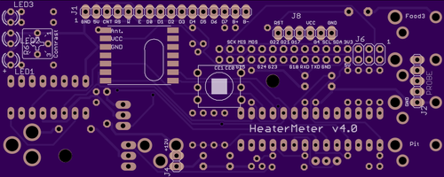
Anyway - here is what a mini module may look like.
I got Eagle installed and all the new libraries loaded
That big square is a playing card - 2.5 x 3.5" for reference.

-methods
What you were missing was a low pass filter right? A cap to ground will smooth that pulsing signal out just as well as an inductor inline. Did you have any low ESR ceramic caps on your input and output of that PWM circuit? Of course it is going to look like hell on wheels with no caps or inductors...
I have quite a bit of experience driving PWM into Batteries (charge controllers - 105V @ 30A) and I think this application is similar.... I dont really care if my output looks like a smooth VCC/2 when I output 50% duty cycle - all I really care about is not burning up the silicon in my mosfets when I turn them on into a virtual short circuit (bank of ultra low ESR controller caps). So when I put out like 1% duty cycle I realize this will be a harsh current spike for the controller caps - but it will be short and sweet - so neither the caps nor my fets will get hot. I will use experimentation to find the rate at which I can ramp up and I will use a ton of ultra low ESR ceramic caps on either side of my switch to eat all that noise.
I may end up having to bring in V+ and GND to implement capacitive noise control... but I will worry about that when I get there.
Anyway - here is what a mini module may look like.
I got Eagle installed and all the new libraries loaded
That big square is a playing card - 2.5 x 3.5" for reference.
-methods
A Peltier is a resistive load, and therefore there's no problem in driving it with PWM and getting what you want. The Peltier doesn't care about the current being constant or not and, for a Peltier, 24KHz PWM is just a waste of energy (switching at the MOSFETs) unless you really need very high precision - the reaction time is "long". With 50% duty the Peltier will give half it's rated power, since it will be ON half of the time. The final effect (heating/cooling) is the same. The only difference is EMI, but I don't think you're too worried about that. Normal home oil heaters and a bunch of other stuff works like that, that's just ON/OFF.
On a motor we don't want torque ripple, and the inductance will prevent us from making it ON/OFF anyways.
On a motor we don't want torque ripple, and the inductance will prevent us from making it ON/OFF anyways.
Similar threads
- Replies
- 13
- Views
- 879
- Replies
- 8
- Views
- 509