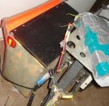
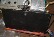
Amberwolf's DayGlo Avenger, MkII

amberwolf said:
oh, definitely. :)

the wu needs new wires on it; they're kinda short :p

HAHA yeah soz about that, needed to reclaim my 8mm gold plated bullet connectors i didnt have any spares too hookz up the Turnigy, figured you would be pulling it apart anywayz so didnt really matter much :)

KiM

p.s you tried any of the software yet?
 
no need for apologies! :)

i have so far only tried the picresizer, which has advantages over the at32resizer i have been using for batch resizes, but not anything else yet.

i need to clear off space on my laptop to install the stuff, so that i can do the work there and be able to work on it when i am out of hte house as well. with the dogs around and sometimes my insane sister, it is too hard to concentrate on both learning new software and designing something in it, so i'd like to take it somewhere else i cna sit for a few hours and concentrate, when i feel well enough to do that.

good news is that garlic oil capsules seem to be helping with what appeared to be a possible infection in the finger yesterday; it got way better after about 12 hours of taking one capsule an hour (though i felt wierd after the first 6 or 7), now i'm taking one every couple hours and it has been pretty normal all day. i kinda feel better in general, too, though not enough to get back to projects.
 
amberwolf said:
good news is that garlic oil capsules seem to be helping with what appeared to be a possible infection in the finger yesterday; it got way better after about 12 hours of taking one capsule an hour (though .

BONUS with the large amounts of garliiic, twill will keep the vampires away from you :mrgreen:

Yes the pic resizer is neat app...dont forgetz to instal the SketchUP Pro too ... has
some options not available on the 'free' version...the other CAD programs
will prolly be a bit mnuch for your needs but you got them for whenz you
find a cnc mill/lathe on the curb<--wouldnt put it past you hahaha

KiM
 
Always the possiblity I'll computerize the lathe I've got (which *did* come from Freecycle). :)


So far DGAmII is working pretty well. I'd like to up the controller voltage to use the 24V and 36V NiMH packs in series, for more Wh total, though. I'm working out what's needed to modify it in another thread:
http://www.endless-sphere.com/forums/viewtopic.php?f=2&t=16740

Today it hauled the trailer full of 120 pounds of dogfood home against some mild winds, with little pedalling as I was too tired to help it much. Well, I pedalled all the time but in a gear too low to effectively help it much, if at all. :)

Took 2.2Ah for the 5.5 mile trip, about 71Wh, over 2/3 (maybe closer to 3/4) of that for the trip home loaded up. I don't have the exact numbers because I fell asleep after I came home and put the food out of dogs' reach. :(

Interestingly, this total power is lower than the previous trip with less cargo, when I pedalled harder! The reason is probably because of the bearing problem previously, and the tire pressure.

This time around, I had about 45PSI in the right tire, and I had replaced the whole left wheel temporarily with the solid-tire wheel I had once planned to use as the front wheel for my ReCycle that I never finished (the very first custom bike I ever tried to build).

So the trailer didn't add as much rolling resistance even with the load as it had done with the missing left wheel bearings and low tires. :)
 
Lots of stuff hasn't happened last few days that I intended to, with Hachi getting parvo and having to find places to borrow money to pay the vet bills, take her to the vet and back, and basically stay with her as constantly as possbible up until the last 14-15 hours or so (she's getting significantly better, but still not out of the woods).

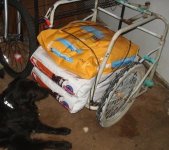
But I did take a few pics. Earlier this week I got one of the trailer with food on it (and Bonnie "guarding" it):
DSC02568.JPG

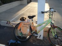
And of Hachi on the trip home from her overnight stay at the vet's:
DSC02572.JPG

DSC02569.JPG

More on this and the other projects once I have time. Some are going to be slowed down due to lack of *any* funds for stuff for them for a while, unless my usual luck holds of finding bits and pieces that will work out of other things. ;)
 
^^ you can't post a pic like that and not tellz us what they is all gawkin at!! I know
the guys second closet to camera is spewing he cheaped out and bought a ladies bike along and/or
that he didn't grow to be 6.6ft haha

KiM
 
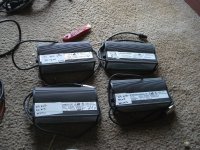
Ian's care package showed up today; I haven't done more than look at what's there except for the throttle and the 24V (working) and 36V (dead) NiMH chargers.
DSC02593.JPG
View attachment 2
DSC02595.JPG

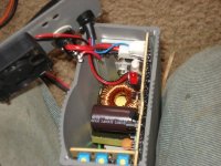
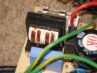
Both of the 36V chargers have blown primary input fuses (fast blow 3 to 3.5A as marked on PCB). One of them also has the ferrite core of the main SMPS supply cracked apart and floating around inside; I suspect that may have shorted something, don't know. It still had what was probably the original 3-pin mini-xlr type connector. I haven't looked into what else might be wrong (before I just replace the fuse and power it on).
View attachment 3
View attachment 4
DSC02599.JPG

The other has had it's original connector removed and small Anderson powerpoles installed. Since in addition to the primary fuse blown it had a smell of burnt electronics I looked around at the primary side first, and found the AC-input rectifier cracked as if it had overheated very very fast and vaporized something inside (like MOSFETs tend to do). The crack isn't visible except when looking really closely at it, and my camera won't focus on the part well enough to pick it up. I couldn't find anything shorted down the line that would cause it, so I replaced it with a nearly identical one from a blown PC power supply, which I also swapped over the fuse from.

Powered it on and no smoke, lights on as designed and labelled, so I hooked it up to my 36V NiMH just by holding the wires to the input of the watt meter, and it began charging at about 4A (the charger's rating) at about 45V, which all appears normal. Disconnected it and began working on making actual connector setups for it all, as well as fixing a potential problem: when they painted the cases, they also sprayed the inside a little, so the heatsink of the PCB-mounted FETs on both primary and secondary sides is not going to be making good contact with the aluminum case, and thus the only heat path out will be via airflow from the fan in the end of the case.

I scraped and sanded the paint off the inside of the case where the heatsink contacts it, filed down the raised lip around the screwholes in the case and the heatsink so they'll sit flat against each other, and put some heatsink paste on there to help since it still doesn't sit flat due to the angle of the heatsink vs the PCB and case, and the fact there's only one screw to hold it to the side of the case. This should improve reliability/longevity of the charger as a whole, though I may never know if it does or not. :) Sorry no pics; I couldn't get the camera to focus on the heatsink or on the case--it was just a blur. :(

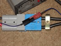
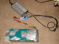
I ended up with the little black anderson off the charger (it's presumably red one is missing the shell) and the red anderson off the 24V NiMH pack (it's black one is cracked apart) on the thermistor wire at battery and charger end, and my regular big 60A andersons (from the UPSs and powerchair stuff) I have on everything as the charger's power output. That way I can hook the charger directly to the battery or I can put the wattmeter between battery power and charger power, and still leave the thermistor wire connected for charging.
DSC02601.JPG

DSC02600.JPG

I had mostly charged the battery via trickle charge overnight, but since I had drained it a lot more than usual yesterday, it still had several hours at least to go when I pulled it off the Sorensons and started this stuff. By my calculations I had put back in 2.5 of the 3.4Ah I'd pulled out. So I put it on the "new" charger, and let it go till it turned green, and got about 0.9Ah into it, in just about 15 minutes or so, before the green light.

That's about exactly what I had estimated it'd still need, so I must have been charging it about right even just with the Sorensons, by recharging with 1.5x whatever Ah I'd used in the riding that day. Nice to know for future reference. :)

Both charger and battery do get quite warm, though. Not hot, really, but a lot warmer than most of the times I've charged it. Oh, and the fan in the charger was making a loud chirping; I can tell there is something fallen inside it's inner housing but can't see it. I'll fix it later; for now I just swapped the fan off the other 36V charger. I just have to keep an eye on it to make sure the thermal cutoff actually works, so it doesnt' cook the pack. :)

So now I have a portable fast charger for DayGlo Avenger, which greatly extends my potential range, especially if I have to go to a destination I will be at for a couple of hours or more (the charger will be able to fully recharge this pack in about two hours even if I ran it down to LVC, I think, depending on thermal cutoffs/etc).
 
wow, fixed already, you are the guru... :D

So I see you fixed the 36 volt charger that has the V on it - so it was the one I used to charge the Voloci, that worked well until it stopped working :(

the other 36 volt charger marked N in marker , that one did tend to heat the battery much more I believe and had a ? loose connection where it would sometimes not sense a battery attached and not charge. ( and then eventually I broke it further by reversing polarity)

I am so glad you could rebuild and use the stuff. and may be sell the 24 volt ones if you dont need them.

i hope Hachi is hanging in there that puppy is so damn cute.
 
ianmcnally2 said:
wow, fixed already, you are the guru... :D
Sometimes. :) Sometimes I never figure it out, even when it ends up being something simple. :roll:


So I see you fixed the 36 volt charger that has the V on it - so it was the one I used to charge the Voloci, that worked well until it stopped working :(
I suspect that the crack blown in the rectifier (and it's smell) was a sub-symptom of the fan problem. Since the fan was not spinning as fast as it should (and probably sometimes wouldnt' spin at all, at a guess, if whatever is stuck inside it moves around), it probably got a lot hotter inside than it could take, and stuff affected by the heat started pulling more current than the rectifier was designed (or at least manufactured) to take, and then that blew before the fuse did, and (then the fuse blew, too).


the other 36 volt charger marked N in marker , that one did tend to heat the battery much more I believe and had a ? loose connection where it would sometimes not sense a battery attached and not charge. ( and then eventually I broke it further by reversing polarity)

At first I was confused by this because I thought that I had fixed the one with the Andersons on it but then I remembered that I swapped that whole end to change the fan since it was easier. :oops:

I haven't tried anything on it yet, but I am going to guess that the broken ferrite core of the transformer in it is affecting current flow or voltage or both, at the primary side. That probably means it is outputting a higher voltage than it should based on the symptom of heating the battery more.

As far as I can tell based on the behavior of one of the 24V chargers and the V-36V charger, if the thermistor wire (blue on the 36V and white on the 24V) isn't hooked up it won't try to charge the battery; thinks it isn't there. It does still output a high enough voltage to trickle charge a battery very slowly, at about 9mA, just as it does after the green light comes on for "charge finished".

The blue wire that had been on the N-36V charger is definitely ok from end to end, as I'm using it on the V. So either the connection problem was fixed when you changed to andersons and a spade, or it's at the PCB end (which I haven't checked yet).

I am so glad you could rebuild and use the stuff. and may be sell the 24 volt ones if you dont need them.
I can actually use them, too on my 24V 13Ah NiMH pack, and on those three 24V round blue wheelchair power-assist packs, which I am going to try to parallel together via power diodes. Then I can use either or both of those 24V packs in series with the 36V to run a voltage-increase-modified controller to see what the Fusin will do like that, for range. I'll most likely restrict the throttle mechanically to keep from going more than maybe 2/3, so I don't overrev it or potentially damage the gears.

Speaking of throttles, I may try the one you sent on DGA, since I think it will be easier on my hand than the grip is (due to my still-painful sprained pinky--the whole side of my hand aches all the time and hurts when I grip things). Just gotta figure out how to space everything so it'll all fit where I can reach it.

I have looked at the controllers but not attempted to open or hook them up. I do find it odd that (like the Curtis) the designers chose to more than double the problem of getting heat out of the MOSFETs. The FETs are bolted to individual black-anodized aluminum blocks, which are bolted thru insulating pads to a large thick block of black-anodized aluminum, which is then bolted to the actual heatsink (also black aluminum). That's a lot of heat transfer gaps to cross. :( At least one of them is totally unnecessary, too, AFAICS.

I'll probably end up eliminating all the extra steps if I find no specific reason for them to have done it that way, when rebuilding one of them to run at higher voltage. Since there are several of these, and they look mostly identical, I'd rather do my first controller modding on them than the Fusin, and see if I can run at the 60V that my packs add up to that way. Then if I blow something up at least I have more spare parts. ;)

These all look like analog controllers, which ought to make them easier to troubleshoot, too. :)


i hope Hachi is hanging in there that puppy is so damn cute.
She's almost normal now, behavior-wise, but still barely eating. She *wants* to eat everything in sight, but can actually only get a little bit of soupy chicken and rice down before she looks like she is gonna give a refund. ;) And she's still dishing out soft-serve at the other end. :roll:

She *is* adorable, though, even when she's really sick. There's some pics from a day or two ago (time is all wonky right now) on my http://dogsonmystuff.blogspot.com picture site, including the ones above with her in the cargo pod (which are from last week, as we left the vets').
 
The charger has been performing well so far. Didn't get to working on anything else yet, except that I was going to test out one of the 24V chargers on my 24V pack, but I seem to have lost the thermistor I was going to use to replace the broken/missing one that caused it's original damage. :( The charger will only trickle charge at 9mA when it doesn't detect a thermistor, so...I gotta relocate the thermistor, whereever I put it. :roll:

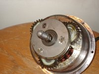
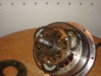
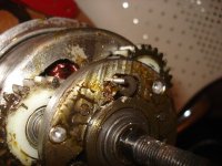
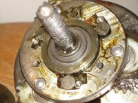
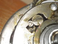
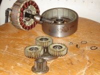
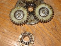
So instead I decided that since I have over 100 miles on the Fusin, I'd go ahead and try to disable the freewheel so I can test out regen on it. As I don't want to permanently disable it, not knowing how the test would turn out, I just wanted to block the recesses the freewheel's jam-rollers (what it uses instead of ratchet pawls) retract into when it's freewheeling, so they're forced to hold onto the core in either direction of rotation.
DSC02602.JPG
DSC02603.JPG
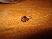
I didn't want to have to fab something, especially since I'd have to do it three times, so I went hunting for something that would fit by itself, unmodified. That didn't work, but I did find something very close, only requiring a bit of filing on two sides: the little hex retainer nuts on PCB-mounted DB-style connectors from old dead motherboards.
DSC02607.JPG
I ended up filing about 1mm off each one total, half on each of two opposing hex sides. Then I cut off the threaded screw on each so they could be fully inserted down into the recesses. I left the springs that normally help push the rollers onto the core in place so nothing could pop out of place.
DSC02617.JPG
DSC02618.JPG
DSC02625.JPG
Since the cover of the freewheel/gear assembly is held on by swaged pins, which I couldn't reswage, I tack-welded it on instead, at three tiny points around the edges.

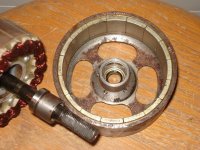
It all went fairly easily, except that despite all my precautions I managed to get a tiny sliver of metal into the magnet/stator airgap, which I knew I'd better remove before I used the motor and damaged it. I should've pulled the assembly off the motor first, to prevent any bits of whatever I did to it from getting into the magnets/stator.
DSC02626.JPG
That went ok, though even with a puller it's pretty hard to get the magnet assembly away from the stator lams! No crunched fingers putting it together, either, fortunately, though it was close at one point.
DSC02627.JPG
DSC02628.JPG
Reassembled it, remounted on the fork, and did a quick test with the bike still upside down, and just running it up to full speed and then letting the throttle off regened about 500mA of current for a half second or so, though it didn't seem to appreciably slow the wheel. I suspected even then that my blocking bits weren't working well enough.

A road test confirmed that--every so often I could feel it grab a bit, and I'd see the wattmeter show some few dozen mA of current, but that's it. There *is* enough friction to be noticeable when coasting compared to what it had before, but it does not have enough to cause it to fully engage and spin the motor, most of the time. :( I guess I'll have to take it apart and redo it. Later, cuz I'm worn out now.
 
It's kind of strange, but all on it's own the freewheel lock seems to be getting "better" as I ride it, especially as I ride without motor assist, just pedalling but with controller turned on. I still haven't gotten more than 50mA of regen current regardless of speed I'm at and of what voltage the battery is at, which seems odd. It also doesn't quite feel like there's the same drag on the wheel forwards as there is backwards, and AFAIK they ought to be the same if the freewheel truly was disabled--so it probably still slips at some point.


Another tidbit is that I had to swap throttles, for more than one reason.

First, my sprained pinky still hurts pretty bad while I'm trying to hold the twistgrip throttle at max, since I have the throttle flipped (so I can use it with my gripshifter) and I have to hold it with that edge of my hand.
DSC02454.JPG

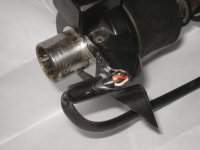
Second, I have had some cutout with it periodically for a while, but after the little spill a few days ago that broke the plastic wire support, it got much worse, and on my way home from work & grocery shopping yesterday, it simply failed completely. I'd hoped it was just a wire, but it is the power and signal leads at the hall body that are broken. :(
Throttle tip broken by abdominal owie.JPG

For the latter, I could just move the hall out of another throttle, or scrape away enough plastic on the hall case to resolder to it, but I prefer to also fix the first problem, and try out a thumb throttle, which came from Ianmcnally2.

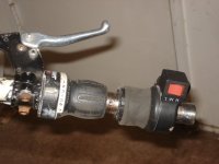
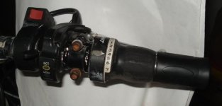
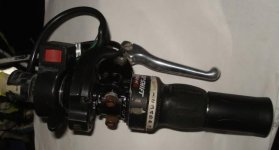
But...the high/medium/low switch is part of the throttle, so it's not quite that easy. I ended up removing the twist grip and spring from it, setting them aside with the broken hall sensor for later reuse, and sliding the whole assembly (still flipped) onto the inside of all the other bar controls on the right, with the switch itself flipped so low is on the right side now.
thumbthrottle rider view.JPG
Then the thumb throttle, upside down because I prefer to push forward with my thumb, the brake, and the grip shifter, and a half-grip to cover the end of the bar.
thumbthrottle topview.JPG
 
Throttle and stuff works a lot easier in the new arrangment. :) Much happier.

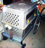
A couple pics I stuck in the pets thread too, showing the multipurpose cargo pod:
file.php


file.php


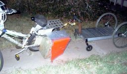
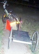
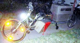
She won't fit in that anymore, though, (well, just barely), so now it is time to finish up a flatbed trailer I started some time ago, and have worked on several possible hitches for to use with CrazyBike2, and never really found one I was happy with. I may have it finished in the next day or two, depending on how things work out with some controllers and stuff I'm also repairing/testing, and ideas for CB2's drivetrain itself. I'll have pics here then.

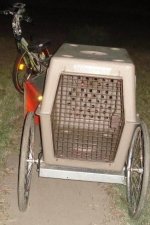
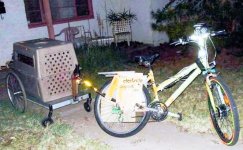
The trailer will be primarily used with DGA for now, so I'm just going to put a stem hitch on it to use the existing DGA setup for the old trailer, so I can use either one as needed. Then I can put the dog carrier on the flatbed, bolted down, to take up to two of them (depending on which ones) to wherever I need to.
 
Finished the trailer and tested it ok; its kinda noisy so I'll probably add something to the underside of the metal faceplate the flatbed is made of to dampen that. Maybe sprayglue some dense foam on there.

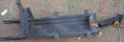
First up was making a simple and light hitch to use the original hitch point on the DGA. I figured a simple neck of square tube and an angle forward should work, and found I had what was needed already laying around. Neck and headtube off the old ScootNGo carcass:
DSC02649.JPG

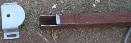
Some square tube for the vertical mast, notched to fit with a 1/4" thick steel piece off of some stickshifter a friend gave me out of his old van's leftover stuff:
DSC02650.JPG
DSC02651.JPG

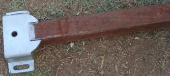
This is how it fits together:
DSC02652.JPG
DSC02653.JPG

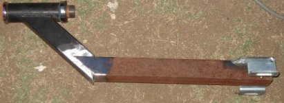
Then after welding the parts together, it's bolted to the front edge of the flatbed, and then slips over the stem that is the hitch on the back of DGA:
View attachment 7
DSC02655.JPG

The flatbed itself is a faceplate off an old mainframe computer (or rather, a communications interconnect panel from between sections of such a computer). It happens to be identical to a panel once used in Engineering / Torpedo room on the movie version of the Enterprise, in one of the first three Star Trek movies. :) The wheels are quick-release wheelchair wheels in back, and the pivoting caster wheels off the same chair in front.
DSC02657.JPG

Test-fit shots of the dog kennel on the flatbed, not yet bolted down.
DSC02658.JPG
DSC02659.JPG
DSC02660.JPG

After bolting it down and adding reflectors and 3M reflective sticker tape to strategic points:
DSC02661.JPG
DSC02662.JPG


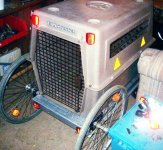
I can use the kennel without it's top half as a "basket" for hauling things if necessary, or just the flatbed, or the whole kennel for taking the dogs on a trip or for hauling things in. Even with the whole kennel on there, it's just barely as heavy as the old trailer, I think (haven't weighed them for comparison).


Now I just need to add lighting to the trailer, and come up with some remotely-actuatable brakes for it.
 
I realized after I got some questions about the trailer that I had not posted pics of the bike-end hitch. :roll:

Basically, it's a U-fork off a 26" bike, with it's dropout ends bolted to the accessory hardpoints on DGA's rear dropouts. Part of a cheap steel stem is inserted into that, but not using the jamnut/wedge. Instead, a piece of allthread has a washer (the same diameter as the inside of the steering tube on the fork) trapped between two nuts and lockwashers at it's far end, and the washer is welded to the tube at two points on it's edge by having drilled a hole in the tube so I could see the washer and ensure a good weld to it.
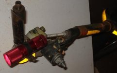
DSC02670.JPG

Then the allthread is fed into the stem, as the stem is inserted onto it down into the tube just like normal, and a nylock nut on the allthread pins the stem into the tube so it can't come out. A second stem, this one off a BMX type bike, is placed with it's handlebar clamp parallel to the first stem's clamp, and a long bolt is passed thru them both, with a few washers about the same size as handlebar tube along the bolt within the clamps, to give the clamps something to hold to and keep the bolt from wiggling around. A larger washer between the stems prevents binding, and at least one at each end holds them together.
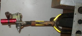
DSC02669.JPG

It is quite stiff to move by hand, but the weight of the trailer easily moves it around. Stiffness makes it easier to attach the trailer, and keeps it from bouncing around when I ride without the trailer. The trailer simply is lifted down onto the upward-pointing stem, and the stem bolt is tightened to keep the trailer from being removed easily (it probably could never fall off unless a bolt shears). The red flashlight is a taillight to mark the stem, just hoseclamped on. (I do not yet have regular lighting back on DGA). Also has 3M reflective tape on there. I only have yellow and white, so white is used up front half of the bike, and yellow in back. Rather have red, but I use what I have. :)


You can also see the rest of the fork and where it goes to the dropouts. There is a diagonal brace from the fork to the right side panel that prevents it from vertically pivoting; this is so that my two-wheel trailer will function. The four-wheel does not need this, so I could take it off if I wanted better leaning ability, but it needs to stay for backwards compatibility with the other trailer.

Any weight capacity tests yet?
I originally tested the idea of the trailer way back by bolting on the quickrelease wheelholders and the casters, snapping in the wheels, then standing on the bed and gently hopping up and down a little. I figure that with my ~150lbs plus gravity I probably put 200+ lbs onto it like that, for a static test. The faceplate bows a little because of the concentration of all that weight in one spot, but nothing gave.

I couldn't do load tests with previous hitches because their turning ability was too poor to continue with them. Another problem is that the hitch I most wanted to use, the crutches extending out the front from underneath, level with the flatbed, with the headrest balljoint at the bike, shimmied a lot when over about 8MPH. I'm not sure why.

Now that a hitch works, having the ~10lbs of kennel on there plus Hachi (~55lbs now), it works fine, although when she wiggles around in there it's hard to ride straight. It has not been tested with this hitch at speeds greater than about 10MPH though, nor on rough roads, just around the block at home.

I plan on filling the kennel with all the lead-acid batteries I have, and anything else small and heavy, like transformers, etc. Then testing it around the block at various speeds, and trying to deliberately run it into the rougher edges of the roads.


Does the hitch assembly limit the ability to lean into turns?
Not much. With the two-wheel trailer it did not limit it at all, since the front of the trailer could dive down a little to compensate for the lower hitch height during the lean.

With the front wheels of this trailer preventing that dive, I probably can't lean as far in a turn as otherwise, but I can fix that by altering the mount of the bike-side hitch to allow vertical pivoting. I could not do that with the two-wheel trailer or it would just drag the front on the ground.

That said, most of the time when I'm pulling this trailer, I'll likely have it loaded up enough to not be going fast enough to require much of a lean on turns. :) Or I'll have the dogs in it and be trying to give them a comfy ride rather than an exciting one. ;)

I can still use the old trailer for anything that might require more leaning, but I might end up preferring the new trailer over it. We'll see.
 
Another question I got (on FBN) about it:
are the front trailer wheels always on the ground, or just for rolling it around when it's not on the bike? seems like when you got up to a regular biking speed they'd rattle like shopping cart wheels.

That's a good question. At the moment they are setup to be on the ground all the time, but only lightly when I am actually on the bike, not taking the full weight of the front.

I have it setup so I can still raise the front of the trailer another 1/2" or more at the hitch, plus another 1/4" or so at the point the hitch post bolts to the flatbed, so I can easily make it so that it will always clear the ground. Or I can lower it so that the wheels all always fully rest on the ground.

I thought about making some sort of lever to raise/lower the front wheels, but decided not to do so since it would add more weight and worse, more complexity; I wanted this to be a very simple trailer.

One potential issue I have yet to test for is speed bumps--the narrow ones in parking lots and the like. They may be a problem--the flatbed itself has significant flexing ability, so it might be ok, but with a heavy load it might not be possible to go over them due to the front wheels' small size, without getting off the bike so the rear of the bike can lift a little with them to allow passage.
 
Yes, they did. :) They're a little worse for wear, but still work. So did the badly-worn rear wheels. I still have the (well-worn) red aluminum frame, which will probably become the front cargo frame on the trike if I ever get the dang thing designed and built. :)
 
DAMN! so you 'found' a Quickie wheelchair fark me, mine cost close to 3k haha tiz
the only one i didn't snap the frame of in the first week...took few months haha
How are you going to stop people stealing your wheelz though? The quick release
hubs are excellent...on a wheelchair...but they take seconds (literally) to remove...
Hate to see you come out with 500kilo of Dog Chow and find a trailer with no wheels
sitting there haha

KiM
 
AussieJester said:
DAMN! so you 'found' a Quickie wheelchair fark me, mine cost close to 3k haha tiz
the only one i didn't snap the frame of in the first week...took few months haha
What was left of the one I have was donated to me for the bike projects, as it was going to be thrown away otherwise. Take a good look at the wheels and you'll see some bad wear, including a missing (was snapped) spoke on one rear wheel. You can't see it but one of the caster forks apparently had a loose bolt for probably *years* of use, as it's axle bolthole is worn into an ellipse about twice the length of the original diameter. I also had to pull out about 10 miles of hair out of the bearings. :( There is actually almost enough of the chair to use as a wheelchair, if I ever needed one. I also have a cheapie that my mom used when she was in her last months, but it is plastic wheel hubs and heavy chromed steel frame, etc.


How are you going to stop people stealing your wheelz though? The quick release
hubs are excellent...on a wheelchair...but they take seconds (literally) to remove...
Hate to see you come out with 500kilo of Dog Chow and find a trailer with no wheels
sitting there haha
Yeah, that would be bad. :lol: It was one of the first thoughts I had about using these wheels--originally I was going to use them (with smaller rims and bike tires) as my trike's front wheels, before I decided on the front-wheel-motor-drive idea.

The idea is I take the wheels off myself and either take them in with me if I'll be a while, or cable-lock them to the bike itself. ;) I have a second extra-long cable and lock to run just thru the trailer itself, and the kennel door and plastic sections, so that won't disappear so quick either. Kinda depends on the area I'll be in.

My old trailer looks so crappy I'm not worried about anyone ever wanting to steal it, but this one actually looks kinda nice, relatively speaking, so I am a bit more anxious about it (especially since I couldn't just build another one out of the junk I have laying around, unlike the old one).
 
amberwolf said:
I also had to pull out about 10 miles of hair out of the bearings.

HAHAHA yup thats same as mine they didn't even bother trying to get the hair out of the last set binned them and fitted new bearings
Government pays for the servicing of the chair mobile mechanic comes to my house and does it all for me too :)

What you needs is a set of chepo wheelchair hubs although, the ones your using now are much stronger
the hollow axle design will bend (although i have never ::touch wood:: broken or bent one of these quick release axles) where as the solid threaded axles in cheap chairs just snap on the thread, broke half a dozen of them easy with my first few chairs till i got the Quickie.

KiM
 
According to someone I know that services these, the QR axles, while hollow, are titanium and are rated to support at least 600lbs of weight. The rims and/or spokes should bend or snap long before the axles do. :)

I'm pretty sure the trailer flatbed itself would not take that kind of weight without bending or cracking as it is right now, since it's just ~3/16" aluminum folded into an open-backed box shape, welded where the edges meet.

Once I determine if it's necessary I'll add an internal frame to stiffen it, but I'd rather not add weight if I don't have to.
 
The flimsy lid to my cargo pod has been giving me trouble for a while, and I have meant to replace it for more than a YEAR, so it would be A) more secure and B) more rain resistant.

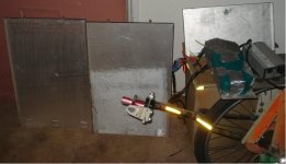
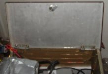
Today I finally did that, using some covers to rackmount servers (or something) that I was given a while ago. They're aluminum, and already have folded-over edges to both stiffen them and to help enclose whatever they cover.
DSC02673.JPG

Oddly enough, they're also almost exactly the same size as the box I used for the cargo pod. Not too much of a coincidence, really, as both were from rackmount equipment, but not every box is exactly teh same size in equipment I've seen (or got).
DSC02671.JPG

In this case, I did have to "shrink" the top of the box a couple of millimeters from side to side, so the top would completely close and let me lock it (using the cabinet lock I used to use on the original lid). To do that, I just hacksawed down into one corner of the box a couple of inches, to leave a slit that let me bend the side inward a tiny bit. The outer (side) face of the box bolts on, and has slop in the holes for the bolts, so it still fits without modification.
DSC02680.JPG
The hacksaw point is visible as a silverish line near the bottom center of the pic, vertical at the corner of the box closest to the bike wheel. Ignore the battery and charger sitting on top of the rack.

That original face has slits in it, which at the moment are covered by tape on the inside and by the orange construction flag on the outside, but are still nowhere near rain-, tamper-, or dust- resistant. However, the leftover piece from the lid made above happens to be almost exactly the same size as this part of the box--it's about an inch or so longer than is required, but that's easily cut off. And it has no holes, so it will seal it all up. :)

A pic of the top of the box, with lid partly open. Also visible in the pic on the right lower corner is the Andersons of the charger and battery hooked together, with the little bitty Anderson used for the thermal sensor on the NiMH pack.
DSC02672.JPG
The cabinet lock I used is seen clearly. What I'd like to do is use at least two identically-keyed locks on it, one closer to each corner rather than one in the center, to make it a little harder to pry open.

Now, if I could only get some of those IBM AT-case keylocks *with* keys, I'd be all set.

I do have some keys for that type of lock, but not the actual locks they're for, and I have some locks but not the keys for them. They appear to all be unique keys, so I can't use any of them yet. Also, they're not the cheaply made kind of cylindrical key lock--these cannot be opened simply by pushing in all the pins (like with a pencap); they have to be pushed in the *right amount* for *each one*, which is not the same distance for every pin on every lock. Great for theft deterrence, bad for me making myself keys for them. :(

I also have a bunch of crappy keylocks from various other computer cases, but they all *are* the kind you can open with a pen cap, and they're all pot-metal. I could probably break them with my teeth. :(
 
hehehehe. Dude. your posts are hillarious, if you survive the ride, I completely appreciate why you'd colour the bike neon, it puts off any thieves, that made me chuckle. :lol:


amberwolf said:
Ok, well, apparently even with two eyes I can't count. :roll: There are not four rows of eight cells in the pack, there are two of eight and two of seven, and it's pretty glaringly obvious, too. So that's actually 30 cells, not 32, for 36V nominal and 42V to 48V (at 1.4 to 1.6v per cell) charge. Explains why 45V works well enough, as that is the average, while 50V is way too friggin' much. :lol:

So...as long as it's short experience at overvoltage didn't break it, I should now be charging it in a much healthier way. It's at roughly 8.2Ah right now charged thru it since this charge cycle began yesterday; I haven't used it at all today (been in bed feeling sick and blind most of the day, on the computer as it's the safest thing I can manage right now besides petting and snuggling up with the dogs).

Still haven't shortened up any cabling or put the watt meter in the cargo pod, but will likely do that after work tomorrow if I survive the ride.
file.php
 
Back
Top