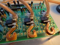
Cromotor + MethTek Monster 24FET + 20S lipo build

Cromotor Hubzilla ordered. :mrgreen:
 
"Diagnose before opening the motor"
Well, I put 5V over the black (g) and red (5+) hall wires, measured volts over the hall signal wires relative to the ground, and moved the wheel. No signal, 0V....
I also measured resistance from each of the phase wires to the brake disc. No resistance...
When I open it up this weekend, I am sure I will not like what I see.
 
hjns said:
"Diagnose before opening the motor"
Well, I put 5V over the black (g) and red (5+) hall wires, measured volts over the hall signal wires relative to the ground, and moved the wheel. No signal, 0V....
I also measured resistance from each of the phase wires to the brake disc. No resistance...
When I open it up this weekend, I am sure I will not like what I see.

the halls could be open-collector types, then you need pull up resistors...

http://en.wikipedia.org/wiki/Open_collector

did you try a sensorless controller with the motor ?
 
Lebowski said:
hjns said:
"Diagnose before opening the motor"
Well, I put 5V over the black (g) and red (5+) hall wires, measured volts over the hall signal wires relative to the ground, and moved the wheel. No signal, 0V....
I also measured resistance from each of the phase wires to the brake disc. No resistance...
When I open it up this weekend, I am sure I will not like what I see.

the halls could be open-collector types, then you need pull up resistors...

http://en.wikipedia.org/wiki/Open_collector

did you try a sensorless controller with the motor ?

No, I don't have one. However, with continuity between the phase wires and the disc brake, I am sure that even a sensorless controller won't be able to make it work.
 
hjns said:
No, I don't have one. However, with continuity between the phase wires and the disc brake, I am sure that even a sensorless controller won't be able to make it work.

Ah, ok, sorry, I thought 'no resistance' was an open connection (so for very high ohmic)
 
Lebowski said:
Ah, ok, sorry, I thought 'no resistance' was an open connection (so for very high ohmic)

Sorry, my mistake. Obviously the phase wires have shorted against the stator. If I ever want to make this motor functional again, I need to rewind it. Should be another nice learning experience.... But only after I get my Hubzilla working!

Hubzilla is in transit. At this moment it is waiting at the Swiss border.... I have another black SAS HALO 26" 36Hole rim + black SEPIM 14G spokes from John Holmes waiting for Hubzilla...
 
So, the postman came today. He was not happy. A small box from Croatia had arrived, and it contained...

HUBZILLA


whoooaaaaaaaa

Now, that is one huge and heavy motor! I like the estethics as well. I don't like the phase wires, looks like 14AWG. I do love the 16mm axle with the 10mm flat. Prospected modifications:

  • Add temperature sensor. I don't want to overheat this big baby, and I want to see whether I need to vent or oil-cool this motor.
  • Replace phase wires with 12 or 10AWG.
  • Lace it with 14G SEPIM black spokes into my HALO SAS 26" rim.
  • Connect it to my 18 FET 4110 Lyen controller that is still in the mail. The controller will be modified as well.

I will post pics later.

Further, I also have the following projects going on:
  • Look into why my front 9C is not functioning well. Need to look at the hall sensors, as described here.
  • Once the 18FET controller comes in, modify it to allow 120A with Hubzilla as described here.
 
Busy night:

  • Took the whole bike apart down to the frame.
  • Searched the internet how to remove the bottom bracket
  • Removed the cranks, bottom bracket, front derailleur.
  • Cleaned every part and positioned to dry.
  • Removed the smallest front gear from the right crank. I could not remove the middle gear, so I left it there.
  • Added a 6-magnet ring around the spindle, to allow for PAS.
  • Took my hydraulic car jack, and very gently inserted it between the rear dropouts of the frame. Positioned it at 160mm and will keep it there. We will see tomorrow how far the frame will go back to its original 135mm. Hopefully it will stay at 150mm....
  • Opened Hubzilla, cut the wires approximately 10 cm from where they exit the bearing, and evaluated the wires. Although the phase wires may be thick enough, I just don't like that very stiff wire with insulation that is easily damaged. I will probably replace with 10AWG rated for 200oC anyway. Main purpose is to add a 10k NTC thermistor, and there is plenty room to add it. Here is where it pays off to have opened and modded a hubmotor before. However, I got tired, and decided to call it a day with the motor. Tomorrow I can continue with it.
  • Took the front fork, taped all the non-paintable parts, and then sprayed the fork with a nice dark-blue metallic. Will dry overnight, and we will see the results tomorrow.
  • Received a PM from Lyen that he actually added another shunt when shipping the 18FET to me. I had NOT asked for that, I only told him that I would use it for my Hubyzilla. Obviously he has anticipated my need for higher currents and therefore a better shunt. Hats off to Lyen!
  • Received a PM from Methods with great advice regarding further modifications. Well appreciated! Methods has been a great help ever since my first steps in the E-bike world. Thanks again, Methods!

Also, I received an email from Grin that my new CAv3beta + Thun torque sensor/PAS may be shipped on Friday. Having removed the bottom bracket from my bike, I know I will need to buy another set of cranks to go with the Thun. My current Shimano Hollowtech 2 bottom bracket is one complete system with the spindle and cranks, and the bearings not exposed, actually very nice. We will see what needs to be done when the Thun spindle comes in.
 
This morning:
  • Removed the jack from between the rear dropouts. The rear dropouts flexed right back to 135mm. :( I guess I will have to remove the disc brake adaptor from the hubmotor and add my Avid rotor directly onto the motor.
  • Grinded the rear dropouts and the DrBass torque arms and made sure everything was metal/alu shining. Cleaned surfaces with alcohol
  • Took my old cheap chinese hubmotor, covered the axle with some thin tape, and positioned it between the rear dropouts. Then covered the dropout surfaces with DP420 and put the torque arms on. Fixated and will let cure for a couple of days.
 
Hjns, be carefull because cromotor is really hard on the dropouts, i would advice you to use some sort of clamping.
Btw when you get the bike running with it you ll never look back!
 
gensem said:
Hjns, be carefull because cromotor is really hard on the dropouts, i would advice you to use some sort of clamping.
Btw when you get the bike running with it you ll never look back!

Hi Gensem,

These from DoctorBass should be ok, right?

file.php
 
If the axle fits really tight on thoses and you can use a couple bolts along the epoxy you should be fine.
 
Hi Gensem,

The axle fits only with a lot of force, which is good. With the narrow tolerances, the torque arms may not be perfectly aligned, but once the axle is in, it will stay in. The epoxy seems to be very very strong. I repeatedly hammered the torque arms to get the other axle off, and they held perfectly. I am not sure I am willing to drill a hole in that metal, and am even more hesitant to start drilling in my frame.

Otherwise, I had a busy night and morning:
  • Further cleaned the frame. I was not able to remove most of the old paint. Due to lack of time, I decided to go ahead and start spraying a layer of primer just on top of it. After some layers and 30 minutes drying in between, I added a nice blue metallic spray.
  • Same for the front fork.
  • Added a 10 AWG phase wires and a 10k ntc thermistor to the motor
  • Testing the motor I had a nice working motor with the first hall/phase combo !!! I have connected the throttle directly to the controller, so no current measurements yet.
  • Build a battery box for 6 pieces of 10S 4.5Ah that fits in the triangle. I started with some cardboard, covered that in the inside with epoxy/resin, added some balsawood on the bottom, and covered the complete inside with glass fiber cloath. Now that needs to cure for a day. Tomorrow the outside.

I like working with epoxy/resin, cardboard and glass fiber. This is my first try, and of course the quality will suck. But I am working from the inside to outside (batterbox inside, batterybox outside, triangle cover inside, triangle cover outside), so hopefully when I do my fourth try, I will have no bubbles and a nice smooth surface. Then paint that blue metallic as well.

Goodies that have come in / will come in:
  • Lyen tester.
  • Freeload rack for the rear. Rated for 25kg. Ordered the side racks as well, but will take some time.
  • SKS chain cover and mud guards. Remember, this is supposed to be a high speed reliable hill commuter, so despite the XC FS frame and HALO SAS 26" rims, I will put the Schwalbe Energizer around them.
  • The Lyen 18 FET 4110 controller is in the mail. Looking forwards to it. Going down in voltage and going up in current.
 
Alan B said:
Another Cromotor conversion. :)

Yes. A lot of work but it is great fun!


Did a lot of work this afternoon. Discovered that I can not find a local source for the 16mm 1.5mm bolts. :evil: Anyone? I must have visited at least 4 different shops / LBS.

  • Put the motor into the frame again and checked how much extra I need to clear the disc brake. I tried removing the adapter, but my Juicy Seven caliper won't fit. Put the adapter back on again, and it looks like I need another 10mm. And that needs to be done with C-rings, otherwise the wires are crushed between the hub and the dropout. Of course, I do not have C-rings that fit a 16mm axle, only for 14mm axle. So I gather 5 of the "normal" closed washers with 10mm flats, and used the decouper saw to remove a part of the ring so that I had a couple of C-rings. I also decided to epoxy them to the axis. A full washer will then be placed between the outer C-ring and the dropout.
  • Laced the motor into the HALO with 14G black SEPIM spokes from John Holmes. These 14G are really much better to tension than the 12G. I like them much better. Tensioned the spokes until all had about the same pitch. Then checked for vertical and lateral trueness by only tightening the spokes. Then did the tension relieve thing by putting a screwdriver between all crossed spokes. Then checked trueness again and listened to the pitch. Any low pitch spoke was tensioned 1/4 turn extra. Then tightened all spokes another 1/4 turn and checked for trueness again and listened to the pitch. The result is a completely true wheel with almost all spokes demonstrating a relatively high pitch.
  • Also, I put the rear shock back on the frame again, and assembled the pivot. I will leave the bottom bracket until the paint is dry....
 
Motor came without nuts. I couldn't find them in the local metal shop, only the normal M16x2.0
Ordered 5 nuts M16x1.5mm at distrelec with express delivery. Shipping is 5 times the costs of the nuts, so I ordered a new Harddisk as well. Always useful.

i_501682f.jpg


They are from messing and only 2.8mm thick. So, I will use 2 on each side. Anyway, they are really only there to prevent the axis from dropping out of the dropouts, so that I can continue the build. DoctorBass' torque arms are more than sufficient to prevent the axle from turning - I hope. :shock:

However, I also ordered these nuts from the UK. These will take a bit longer to arrive, but will be a more permanent solution:
m16-hex-nut-a2-stainless-steel-fine-pitch-4-pk.jpg


edit: replaced "bolt" with "nut". Thanks, Alan.
 
hjns you are probably fine if you dont push the envelope.
My experience with cromotors are plain simple, every simple time i raise the bar something gives... -.-
Now im putting the pedal to the medal using the warp frame hoping it doesnt fail coz i plan to make fun of medium sized motorcycles... :evil:
 
Busy night again. I had really hoped to finish the build in 2 weeks time. Now I probably need double that. Well, here is what was done this evening.

  • Lyen's 18FET 4110 controller came in. Swapped all phase and battery connectors, because I like 5mm gold connectors better.
  • Thought again about the position of the controller. In the end I decided it will go behind the saddle tube. It is the least conspicious place, it is right between the battery box and the motor, allowing for the shortest phase and battery wires, and it is not in the way.
  • Removed the case of the controller and sprayed it black with heatproof paint.
  • Continued with creating the composite glass fiber battery box. It has a nice curve in it and fits in the triangle. Still needs a lot of thought.
  • One torque arm was not epoxied well to the dropouts. I tested it with very brute force and it gave way. I drill-brushed the connecting sides again, filed some grooves in the smooth surfaces, and then drilled a hole. Prepared the DP420, covered the connnecting surfaces with that stuff, and then put a bolt through the hole and tightened with a nut. Then I took a heatblower, and heated the connection for about 20 minutes. Should be pretty strong now.
  • As I moved to singlespeed, I also needed a new wider chain. Ended up with a RED 3/8 chain. Nice contrast with the metallic blue with black colors of my bike now.

Tomorrow I will continue with the battery box and with the wiring. Maybe on Thursday the D420 has cured enough for the motor to be repositioned again. I need to find a way to hide the wires. Maybe a small hole in the frame....
 
Last night I continued with the battery box. I used a saw to open the left side to allow for battery replacement. I had to cover the sides of the box and the cover plate with additional fiber glass in order to protect the exposed inner parts of the box. Remember that I used cardboard, drenched in epoxy-resin. Now it needs to cure again. There is ample room for four 10S 4.5Ah bricks, and if I push a bit, it can fit 6 very tightly. 20S 13.5Ah should be good for commuting.

I added two caps, added 12AWG solid copper wires to the traces, and added a shunt from another controller. Then I tested the new Lyen 18FET controller with 20S. It took some time to find the correct hall/phase combo, but in the end I had a running Cromotor. No load speed at WOT 100% was 95kmh at 2.05A. It is very very impressive.... 8)

I spent an hour or so to try and get PAS working. Lyen provided me with a fitting PAS module. However, no matter how I programmed the controller, I could not get it to work. Maybe it works with the new CAv3 + Thun sensor that is STUCK in the mail. That was the initial intention anyway. So, no PAS via the controller directly.

This is not that important, because I like the throttle better anyway. But Swiss laws allow E-bikes with a Mofa licence between 500W and 1kW to go 30kmh without pedalling (throttle only) and 45kmh with PAS. Therefore it would have been nice to have the PAS working. But I can limit speed to 30kmh and try for a licence.

At that time it was 2300h, so I decided to go to bed. Today is another day, but my wife and kids are coming back from the parents in law, and I need to make the house ready for their arrival tomorrow. So no bike upgrades today.

BTW, I made lots of pics, but prefer to edit, upload, and comment them later when the build is done. Matter of priorities...
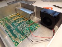
 
hjns said:
BTW, I made lots of pics, but prefer to edit, upload, and comment them later when the build is done. Matter of priorities...

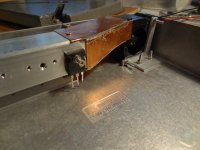
Same here with the controller I'm building to test out on your bike. Lots of warm weather
for swimming in the lake, plus job hunting so controller build is not progressing as fast
as I had hoped. But we'll get there :D
DSC00831.jpg
DSC00840.jpg
DSC00845.jpg
 
WHOOAA Bas, that looks freaking awesome!

With the battery case in the triangle, and the Lyen controller behind the saddle post, I have room for your controller on the back rack. I see 3 inverted question marks where I assume the FETs will come. The question marks are like a sign...... how will this work.....??? :mrgreen:
 
Update - Lyen is helping me with the PAS, thanks mate! I will post the results.
 
PAS is working, thanks Lyen!

The thing is directional. I had the sensor pointing in reverse.

Anyway, I also got the blinkers working, painted the battery box, and started with final wiring. Very happy with the Freeload rear rack with the pannier racks. Very adjustable, very goodlooking. However, I should enable the ebrakes before continuing with hiding the wiring. And I also want to enable a brake light.... So, a couple more nights work...
 
I have a riding bike again.

  • Connected all wires and hid them as well as possible. Brake light works with the E-brake, blinkers work, main lights turn on as soon as I connect my battery (never leave the battery on the bike unattended), and it looks svelte (pics to be uploaded probably next weekend).
  • Started with assembling a single-speed chain without tensioner. It is too long, and keeps falling off, so I need a tensioner. Fortunately, the bike moves when I twist the throttle... :mrgreen:
  • Limited the speed to 41kmh (50% max speed in controller). Wow, that is slow.... however, my range with four bricks (750Wh) is now more than 35km. I would theoretically even be able to do my daily commute on one charge. However, I prefer to have a larger capacity battery and charge at work anyway. Better for the Lipos.
 
First results of my commute yesterday:
  • Settings: 20S2P 84V HOC 9.0Ah, 18FET4110 controller limited at 40A/100A current and limited at speeds 1:30% (Vmax 30kmh), 2:38% (35kmh), and 3:45% (41kmh), 26" wheels, cromotor, CAv2 limited to 40A, current throttle.
  • Configuration: as the triangle box needs more cutting, I temporarily have the batteries on the rear rack. Wheelie machine.....
  • Results: in 3rd speed it is very slow (41kmh max). Torque is great, but I can not really find out because either it will wheelie or I hit Vmax. Still have to calibrate the CA. With standard 2mohm rshunt it seems to eat only 12Wh/km, which is very little.

Bought a chain tensioner and added it. Chain no longer falls off.

Results of my commute this morning:
  • Settings: 20S3P 84V HOC 13.5Ah, 18FET4110 controller limited at 40A/100A current and limited at speeds 1:30% (30kmh), 2:60% (57kmh), and 3:120% (not tested), 26" wheels, cromotor, CAv2 limited to 40A, current throttle.
  • Results: in 2nd speed it is nicely responsive (57kmh max). A Vmax of 57kmh is great for within city limits, and allows me to drive with the cars. Torque is great, and I can still create a wheelie at 40kmh, crazy. Also, I still have to calibrate the CA. With standard 2mohm rshunt it seems to eat 25Wh/km. In reality it is probably more like 35Wh/km.... I did have 5% regen.

Issues encountered:
  • Chain tensioner rubs against the motor when regen is activated. Need to allow a bit more space, and check the nuts of the axle. Obviously the motor is still wiggling around a little bit, hopefully not in the dropouts but maybe just within the limits of its bearings...
  • I have enabled regen. However, the cromotor + controller combo seem to need time to actually activate it. In other words, the first 10 minutes I can activate the E-brake all I want, but it only shuts down the throttle without activating regen. After those first 10 minutes, when I brake the regen is also activated, applying a very nice braking force and very nice regeneration of energy (5%), which is great.
Anyone any idea?

Conclusions:
All in all I am very very happy with my machine. It is not complete, but it's getting there....
 
Back
Top