DIY 6FET Controller help

Hasn't Zombies had success with this mosfet?
could be, i'm not keeping track of who is using what ;)

suggestion still may work though, but for a different reason. different Coss value maybe leads to a resonant frequency that your system does not strike.
 
I'm using IRFP4568's

HighHopes, correct me if I'm wrong here.

If the capacitance or inductance value were to change, the resonant frequency of the entire circuit would change. The only L or C values which would remain the same are the parasitic L and C of the layout itself which make up the natural resonance of the layout without any devices installed. If a standing wave forms due to harmonics of the parasitic LC, there would be constructive and destructive interference. The peaks and valleys of this wave (anti nodes) would be more prominent than normally observed and this type of wave would have to be lower in frequency than the normally observed ringing.

SjwNz should be able to rule out hitting a resonance / reflection issue by monitoring what is happening with his scope. If there is a reflection of a resonant frequency, then the amplitude and frequency of the ringing should increase or decrease out of proportion with small changes made to either L or C.

I realize that MOSFETs are complex devices with lots of changing impedance and LC paths thus providing ample opportunities to ring and interfere. Only good way to figure out what is going on is to scope and change things around.

SjwNz, the ringing you are experiencing is most likely due to a less than optimal layout. Layout inductance is the enemy. The lower it is, the better, but minimizing loop area and changes in the loop area in the gate drive path and in the DC bus path are even more important. Loop area is the #1 enemy. If you would like to learn more about this, study what Maxwells 4 equations are about. You don't have to be able to do the math itself, but you must understand what it represents. This will help you understand the physics at play. If you are interested I can send you some links to Youtube videos I've used to learn them myself very recently.

I believe the 18 FET layout I posted is pretty good in many regards, you can scale it up or down and you only need a 2 layer board. It also has a good thermal path. DC bus is on one side of the board and the phase output is on the other.
 
I was pretty happy with the 300amp gate waveform from the 3 parallel fet test I did so there will be a 18fet controller sometime in the future :)

I have seen a couple of ES threads with 6fet controllers based on the 4468 fet but I dont think any of them did double pulse tests so can not be sure if my gate ring is a layout issue or the 4468 fet is just a difficult fet to use when in a 6fet design. I am not to worried about it , I will just keep playing around with different ideas.

HighHopes, I have ordered some different fets today and will see how these work out as the 2 fets I have selected have 1/2 the
Gate-Source charge of the 4468s (Miller effect) and will be interesting to see what ring freq I will get(if any).

Zombiess wrote:
SjwNz, the ringing you are experiencing is most likely due to a less than optimal layout. Layout inductance is the enemy. The lower it is, the better, but minimizing loop area and changes in the loop area in the gate drive path and in the DC bus path are even more important. Loop area is the #1 enemy. If you would like to learn more about this, study what Maxwells 4 equations are about. You don't have to be able to do the math itself, but you must understand what it represents. This will help you understand the physics at play. If you are interested I can send you some links to Youtube videos I've used to learn them myself very recently.

That would be good if you can PM me those links or just post them here.
 
I did a number of double pulse tests and got up to 300amps (46V battery) and after some playing around with resistor values
and a G-S cap I got this waveform of the gate. The ring freq was 20 to 23MHz in the single fet design and
this 3 fet design droped it down to 13MHz.
Wow SjwNz, I never tried anything 300A, but your last waveform looks very nice, almost clean. What I see is that the 13MHz matches the expectation with 3xCoss, because the frequency dropped from 23MHz by the factor of 1/sqrt(3), provided the layout inductance is almost the same.
One more thing you could try with the same board if you want, because there is much space between your MOSFET rows, to remove the 5 capacitors and solder them between the MOSFETs. Normally it should reduce the main inductance, so increase the 13MHz and further reduce the ringing amplitude, but can't tell for sure. Depends on how much part of the inductance is the layout L and how much is the series L of the capacitors. It is the theory, but only the test could prove or not prove.

Honestly I don't know if your last waveform is due to a fundamentally better layout or a fortunate combination of switching speed and the layout L-s and C-s. At simulations I saw that the ringing amplitude depends on the phase angle at which the MOSFET turn-on/off kicks the LC ringing. In some cases it amplifies the ringing, in other cases it attenuates. Zombiess says something similar by the interference, if I understand well.
It may happen that if you reduce the L or add one more MOSFET, the phase angle becomes worse and the amplitude increases, so I'm curious about the result if you can do the test I described above. Yeah I know giving advice is easy :)
 
don't use this board at 300A and you'll be ok ;P

i think zombies & peters are saying the same thing just using different words. at the end of the day, i think you have learned now what i mean by the margin of error gets smaller as you go up in power, this means high voltage or high current or high both. in this case you test at 300A on a nominal 30A board so that's high power. this board is not good at 300A, at least not yet.

geometry maters as you go up in power, its about trying to find the balance for the power and scale of devices you have. you can not get away with not knowing how to do this as it is so rare to get it correct by chance.
 
HighHopes wrote:
don't use this board at 300A and you'll be ok ;P

Sorry HH , i have been jumping between 2 tests, that 300amp test was done with a 1/2 bridge I made using 3 fets in parallel. I only made it to see if I would get the same ringing issue and it worked way better than my
controller in my bike. But I will continue to work on my small 6fet controller design until I get a clean gate signal with a double pulse test.

Thanks for all your help again guys :)
 
zombiess wrote:
SjwNz should be able to rule out hitting a resonance / reflection issue by monitoring what is happening with his scope. If there is a reflection of a resonant frequency, then the amplitude and frequency of the ringing should increase or decrease out of proportion with small changes made to either L or C.

Peters wrote:
Wow SjwNz, I never tried anything 300A, but your last waveform looks very nice, almost clean. What I see is that the 13MHz matches the expectation with 3xCoss, because the frequency dropped from 23MHz by the factor of 1/sqrt(3), provided the layout inductance is almost the same.
One more thing you could try with the same board if you want, because there is much space between your MOSFET rows, to remove the 5 capacitors and solder them between the MOSFETs. Normally it should reduce the main inductance, so increase the 13MHz and further reduce the ringing amplitude, but can't tell for sure. Depends on how much part of the inductance is the layout L and how much is the series L of the capacitors. It is the theory, but only the test could prove or not prove.

I will try and work on this next week as I have run out of time for the week. got mountain bike racing tomorrow and a motorbike track day on Thursday then back to the farm for the weekend doing farm stuff.

I just finished testing 3 different types of fets on a simple 1/2 bridge board I made and got the same ringing issues. so as you guys have been nicely hinting to me its most liking my dodgy layouts :) I tested IRFP4468(in my 3kw controller), the IRFP4569 and IRFB4110.


I am starting to run out of ideas on how to layout a 1/2bridge.lol
 
did you rule out the ringing being the cause of a big loop in your probe connection?

if not, you could try one of these spring things as a gnd point to make a very small loop
Update202.jpg
 
Futterama said:
What are those called in real life? Can't find them on ebay...

http://electronics.stackexchange.com/questions/40420/what-is-the-name-of-this-springy-type-oscilloscope-probe-accessory
 
nieles said:
did you rule out the ringing being the cause of a big loop in your probe connection?

if not, you could try one of these spring things as a gnd point to make a very small loop
Update202.jpg
With a differential probe those do not work.
 
Zombiess wrote:
I believe the 18 FET layout I posted is pretty good in many regards, you can scale it up or down and you only need a 2 layer board. It also has a good thermal path. DC bus is on one side of the board and the phase output is on the other.

I was hopefully looking at the correct layout, I followed your thread sometime ago but from memory it was a 4layer design?
I downloaded KiCad and open the PCB file on the first page of your My new 18 FET TO-247 layout riding video page 10
and I like how you did your laminated bus using the internal layers.
 
Don't bother with the internal layers, you only need 2 sides. I learned a ton on that build. I now prefer 4 layer boards due to the flexibility they allow, but I only utilize 4 layers on the gate driver traces, but 2 layers will work OK if the bus design is decent.
 
Been looking at buying a differential probe as the one i have been using I borrowed. Was wondering what probes fellow ES members have been using.

I am looking at a used Tektronix P5205 from Ebay but I will also have to get a special power supply to use it which gets the price much higher. ( The higher end Tektronix scopes have special connector for the the BNC and power for the Probe and my lower end scope does not have this )
Or a new TA042 made by pico and is battery powered or can use a simple 9VDC power supply.
Both are 100MHz 1000V and looks like the same CMRR values -80bB@60Hz ; -50dB@1MHz.
 
You might want to consider going with a lower priced option that does not require the power adapter. I have a P5205 and the adapter box myself and you are right, it's expensive. Chances are you will not need 100Mhz bandwidth anyway. Most of the time I have my scope BW limited to 20MHz when doing measurements.

Look at the Pintek probes, you can get them for <$300 USD.
 
I agree. For this application the fastest moving transient that you're likely to measure is the switching speed which is about 200 nano seconds. Inverse of that is 5 MHz. To measure something accurately the device needs to be 5 to 10 times faster, therefore you could argue the probe should be between 25 and 50 MHz. 20 MHz works too I think :)
 
Hmm, why is it? The ringing frequency is 20MHz or more, it is suppressed by a few dB with a 20MHz probe.

Another option is to build a diff. probe. The circuit itself shouldn't be very complex if it is made for a single voltage range. Although tuning and calibration may not be easy, it is another project.
 
I was thinking the 100MHz bandwidth was a bit overkill, but I was wondering if this would mean it would have a better CMRR at the frequency's we are looking at with speed controllers.
With the cheaper diff probes its nice to connect to anywhere in the circuit but would I get more common mode noise issues if I get a lower bandwidth probe.
 
Yes I think so, CMRR at the high ringing frequency is important and a low BW probe is not so good in this regard for sure, but I don't have probles to try now.
My 6-FET controller I'm working on with IRFP4568 rings at 36MHz, so the frequency can be this high, too.
A probe with 40dB CMRR would attenuate a bad let's say 50Vpp noise to 0.5V, so I think 40dB is OK, 20dB is not sure.
Furthermore as I see, the CMRR of the oscilloscope can not be added to the probe's CMRR, because the probe turns the common mode noise into a differential noise (with the attenuation), so there is no common mode signal on the oscilloscope input any more.
 
Lebowski said:
How about just using two (ordinary) channels from your scope and using the subtract option ? Has always worked for me...

Heretic! :mrgreen:

I upgraded to a 4ch since I found a 2ch a bit limiting for the lab work I was doing. Funny thing is my scope is about the lowest cost item. The each of the 4 probes cost more than the scope did, but I view the cost as an educational expense.
 
I got my priorities all wrong, I spent my money I put aside for a Diff probe and got a chainsaw :)
Will get Diff probe early next year now and will get the PICO TA042 which is the 100MHz 1000v unit 1st and then maybe look at getting a cheaper 25MHz probe later on as well. Will be nice to look at 2 different signals at once.

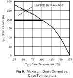
On a different note, about 2weeks ago I fitted a better temperature sensor and it will back off the throttle when the fets get to 80°C. So now that i know I can not over heat the controller I was looking at the Maximum Drain Current vs Case Temperature graph for the 4468.
DS2.jpg

So today I decided to wind the phase current up to 190amps, and left the AvgBatt current at 70amps. Well, it didn't blow up and I rode around the block a number of times and it was great. I have set the phase back to 150amps again but I need 200amps phase now :)
 
SjwNz said:
On a different note, about 2weeks ago I fitted a better temperature sensor and it will back off the throttle when the fets get to 80°C. So now that i know I can not over heat the controller I was looking at the Maximum Drain Current vs Case Temperature graph for the 4468.


So today I decided to wind the phase current up to 190amps, and left the AvgBatt current at 70amps. Well, it didn't blow up and I rode around the block a number of times and it was great. I have set the phase back to 150amps again but I need 200amps phase now :)

Be careful, even better yet, turn it down. 190A is the limit. I would suggest running a 20% safety margin. Running at the limit is flying too close to the sun, wings will be melted. The leg temperatures are going to be way up there too. If you are just making something for fun what you are doing is fine, but it is not engineering a robust controller.

A good analogy is modifying car engines. The stock motor has been tested to work correctly in all sorts of conditions. Because it is so robust, people are able to extract more power from them by trading reliability for performance. I have been able to double the power on several stock Chevy engines, I've seen others triple them to over 1000HP, but there is an extreme trade off because it's now 1000HP for 10 seconds vs 300HP until you run out of fuel, the curve is exponential.
 
Back
Top