icecube57 said:
http://www.ebay.com/itm/45-Celsius-KSD9700-NC-Temperature-Control-Switch-Thermal-Protector-140-Celsius-/330739494289?pt=LH_DefaultDomain_0&hash=item4d019c2d91
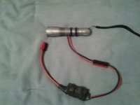
Im going to put this inside the motor and use it 1 of 3 ways. Use it on the ground of the hall wired.
You been spying on my ebay purchase history ?

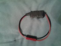
I bought some of these same things a month or 2 ago and have them wired in series with the hall -ve. They're NC so for the most part you don't know they're there until they get too hot and go open, shutting off the halls. People will cry that it's dangerous if it cuts out etc etc but if you melt a winding it's going to cut out just the same, only you'll be pushing it all the way home - and against a fair bit of resistance most likely.
If you're going to run wires externally you may as well just hook it up to a buzzer. The whole point (for me) of using these internally on the halls is to save having to run extra wires externally. And on motors like the crystalytes where the wiring is easily damaged by removing the side cover it's good to be able to pop off the opposite side cover, yank the hall wires up, snip one and whack this in between.
Never mind the critics, they're often the same lot who are scared of lipo burning their house down


.jpg")