Infineon XC846 72V 45 Amp Controller

mikereidis said:
ZapPat said:
Maybe I'll make a mini adaptor board to convert a PIC's pinout to the infinion's, but only if this board proves to be worth it otherwise... :roll: I guess I'll know if it's possible to add regen (and worth it) when I get my controller in about a week.

Adapter board and PIC sounds like a lot of work. Do you have a PIC with hardware PWM or would you do that in software ?

I'm interested in e-braking, but unless I found a controller that does really good variable regen, I'd be more inclined to build a "variable e-brake add-on controller", that just dumps the power to a power resistor or light bulb. Perhaps a red brake bulb under my seat would provide a bit of heat in cooler weather, relocated farther back in summer.

This "variable e-brake add-on controller" would connect to the three phase wires in parallel with the controller. If engaged it must first disable the controller, perhaps through CTRAP or V-Brake signals or any other way to ensure speed controller won't put voltage on the motor.

I read something about an idea to use a brushed DC controller for variable e-braking. I'm not sure how well that would work with AC from motor, instead of DC. Also, would need 3 brushed controllers for all 3 phases. A single controller, would be "ghetto" I presume and the e-braking would pulse and not be smooth.

It seems like a waste though, just ignoring the existing nice 3 phase PWM high-amp and voltage circuitry on the speed controller. Would be ideal if same controller can be used for e-braking.

Check out the PIC18F2331/2431/4331/4431(All the same hardware, just different program memory and RAM. This PIC has VERY similar hardware as the infinion XC846/XC866. The pinout is different though, which lead to my idea of the mini adaptor board possibility.

As for the electric brake idea, I only see this being usefull on a [well designed] regen controller when the batteries are already close to full charge and would not accept more energy quickly. Of course having a warm toosh in cold weather does sound interesting, but maybe it would be better to heat up your handlebar grips instead, since fingers freeze faster than behinds... :wink:
 
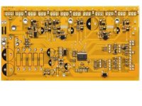
cant help but notice the similarities to the v2 crystalyte ( refly ) board, been a bit of copying going on i think, now who copied who
 
solarbbq2003 said:
cant help but notice the similarities to the v2 crystalyte ( refly ) board, been a bit of copying going on i think, now who copied who

Hummmm, nice photo, solarbbq! But it's very very fuzzy - could you get/take a better one? This does look almost exactly like knuckle's infinion controller. Is it a photo of a controller that you sell, or a crystalyte v2 board?

I'm sure there's lots of design "copying" going on, but it's also hard to even know who actually makes any one controller, and which ones are just buying and reselling ones as their own product... we just love confusion in our "modern" economy!
 
Keywin just purchased the mold for this pcb! He would freak with this post! In a good way. :D

So maybe we continue with ES design and build effort here. I am in! I'll advise Keywin ASAP and we can all get some real JUICE flowing!

This is the coolest engineering effort I've ever been part of. Kudos to all you way-advanced PWM geeks!

Man I don't know sh*t! I am blown away by this knowledge base!

Your Humble Servant,
Knuckles
 
Knuckles said:
Keywin just purchased the mold for this pcb! He would freak with this post! In a good way. :D

So maybe we continue with ES design and build effort here. I am in! I'll advise Keywin ASAP and we can all get some real JUICE flowing!

This is the coolest engineering effort I've ever been part of. Kudos to all you way-advanced PWM geeks!

Man I don't know sh*t! I am blown away by this knowledge base!

Your Humble Servant,
Knuckles

Wonderful. Can anyone get schematics, code, or at least higher resolution photos of the circuit board ? Would be nice to have pics of both sides, both populated and un-populated. Highest resolution, lowest compression possible...

Or just send me a board or two... :)
 
mikereidis said:
Or just send me a board or two... :)
Ha Ha I want the same thing. I'll get some blanks and also some raw populated boards missing fets and power resistors too.

K
 
I dont have any of the boards was just a pic I had and best resolution, I haven't bought any of the boards
 
Hi guys, I'm back! Knuckles, do you have any info about the serial port? I have a lot of good ideas (and now a good amount of spare time :( ) for this project!
:)
 
gip_mad said:
Hi guys, I'm back! Knuckles, do you have any info about the serial port? I have a lot of good ideas (and now a good amount of spare time :( ) for this project!
:)

That will be added in good time.
 
anyone got the colour code for the throttle.
Gnd
Sensor/wiper
+5v approx

Can a hall or a resistor throttle be used
What is the travel to full speed x'tlytes reach full speed at 3/4
 
Cool! But do you have any specs? To start, I can just solder a wire on the chip... No problem! Or just use the already available 60/120° switch wire! Do you want me to develop the Analyst, or will they do it? I would like it to be open source (at least the communication protocol)...
 
Would this controller change the switching frequency of a 48volt, 400 series Clyte hub motor?
I realize you guys are talking about using it for a geared hub, but the 406 motor I have works great except it hits a frequency vibration everytime i accelerate and sort-of shakes the bike as it passes through this stage.

It' sure is great to see controlers and batteries advancing every 6 months.
 
gip_mad said:
Cool! But do you have any specs? To start, I can just solder a wire on the chip... No problem! Or just use the already available 60/120° switch wire! Do you want me to develop the Analyst, or will they do it? I would like it to be open source (at least the communication protocol)...
no specs yet. Darn! It all moves to slow for me (Information that is). :twisted:
But I'll get a unit to you so you can reverse engineer the heck out of it.

-K
 
recumbent said:
Would this controller change the switching frequency of a 48volt, 400 series Clyte hub motor?
I realize you guys are talking about using it for a geared hub, but the 406 motor I have works great except it hits a frequency vibration everytime i accelerate and sort-of shakes the bike as it passes through this stage.

It' sure is great to see controllers and batteries advancing every 6 months.
This is fascinating. Maybe it has a bug? I do not know. The controller is meant for all motors ... DD and geared. Contact me by PM.

-K
 
recumbent said:
Would this controller change the switching frequency of a 48volt, 400 series Clyte hub motor?
I realize you guys are talking about using it for a geared hub, but the 406 motor I have works great except it hits a frequency vibration everytime i accelerate and sort-of shakes the bike as it passes through this stage.

It' sure is great to see controlers and batteries advancing every 6 months.

You mean the "grrrrr" sound that it makes when you accelerate? It's normal, it is because the motor hits the current limit and it "disconnects". If you accelerate slowly, and help the motor with your legs, you won't hear that noise because the motor doesn't ask for a lot of current! It works like the ABS on your car.

Knuckles, I can't wait to put my hands on one of these beasts! :twisted:
I'm thinking about getting 72 volts, so if you want I can experiment with the "standard" box and you don't have to get a 48V specific for me.
Let me know! :D
 
Seeing the discussion on the shenzhen thread... Here in Italy they can get very anal with law sometimes (a guy got a ~3000$ fine for a not-standard ebike :shock: ) it would be nice to implement a quick modification so you can limit the power with a switch.. Here law puts a 15mph limit :shock: and 250w max for the motor.. and you must have a PAS so the motor doesn't run if you don't pedal.
 
Hi all
Just off to the local post office to collect my controller, wasn't in when mailman came will post later
 
gip_mad said:
Seeing the discussion on the shenzhen thread... Here in Italy they can get very anal with law sometimes (a guy got a ~3000$ fine for a not-standard ebike :shock: ) it would be nice to implement a quick modification so you can limit the power with a switch.. Here law puts a 15mph limit :shock: and 250w max for the motor.. and you must have a PAS so the motor doesn't run if you don't pedal.

I think something like that could be done. The PAS part would be more difficult and you'd need some kind of sensor. You could place a resistor in series with the throttle to seriously reduce the maximum. The resistor could be switched in and out. The switch could be disguised, hidden or magnetic.
 
I was actually thinking about decreasing the current limit, so the bike won't start by herself... maybe I can hack the code to use the 60/180° input for the PAS sensor (that I have already installed, but is not connected atm). I still have to think about the switch, maybe a piece of paper that when removed makes the contact, so the police won't notice a piece of paper on the floor...
 
Lowering the current limit would be fine. You could change the gain of the current sensing amplifier.

If you really want PAS, you could use a sensorless setup like a few guys are working on.

You could possibly hide the switch in plain sight. Label it "odometer reset" or something.
A reed switch like the ones used on speedometers along with a small magnet make for a nice hidden switch. Just move the magnet away to turn it off.
 
hi all
I think I have the wiring of the CA worked out, I cross refrencenced with how fechter wired the first china controller also using a CA DP x'tlyte controller I have, with the pictures on justins web site.

this is for use with a puma geared hub,the pinout works for all geared hubs.
So the pinout
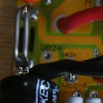
1: Vbatt use a polyswitch and attach to VK2+ or Vcc-L near the orange wire
2: Digital Gnd thick black
3: Analog Gnd thick black
4: Isense shunt controller side NOT thick blackwire side
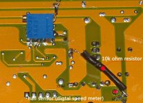
5: Hall external cycle computer reed switch then to a GND pad
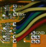
6: Ebrake EBS-
see below
shunt closeup.jpg
the picture below should help with pin 5 and pin 6
brake closeup.jpg
pin 6 goes to EBS- and the hall sensor pin 5 goes to a reed switch then into the controller and is soldered to a GND pad like the one I have shown.


pins 1,2,3,5 I am sure of,pin 4,6 I am 95% sure of
for pin 4 I used information from how fechter attached a CA to the first china controller see post below
http://endless-sphere.com/forums/viewtopic.php?f=2&t=4282&st=0&sk=t&sd=a#p63528
I have put the Isense wire in the same sort of place after following the components to make sure the place matched.
for pin 6 the ebrake I have got it correct if the CA shorts to GND when the Ebrake is applyed, from the 20A controller rewire picture I have got this correct.
hope this helps you guys out there Fechter will you check my pin 4 location is correct.
 
Back
Top