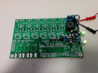
Lebowski controller build possible IPM output stage

Joined
Mar 21, 2014
Messages
53
Hi All,

I am fairly new to Electric Vehicle design and operation with brush less DC motors but I am an EE so hopefully I will pick it up fast but go easy on me as I get there :)

My brother (Bluefang) has asked me to build some Leowski style controllers http://www.endless-sphere.com/forums/viewtopic.php?f=30&t=57877 and see if we can get them running with IPM as an end goal for larger power applications (Hub monster been one of them).

My plan so far is to:
1.) Build a Lebowski controller with Lebowski output stage http://endless-sphere.com/forums/viewtopic.php?f=30&t=55641
2.) Using the same driver chips IRS2186 http://www.irf.com/product-info/datasheets/data/irs2186pbf.pdf drive IGBT modules similar to the Tesla Roadster Power module using the same layout as Lebowski's output stage liquid cooled if required
3.) Remove driver chips and drive an IPM using an external interface board for the Opto's etc required
4.) Modify Lebowski controller board to replace Driver chips with components required for IPM driving and mount board directly to IPM.

I hope to stay away from IGBT modules and their driving issues for high currents/voltages if at all possible by going straight to IPM's.

One thing I know may need some work will be the DC Link capacitor at these power levels but I should be good here as we are doing a project with the DOE at work on this very topic ;) So I will pick the bosses brain about what to use.

Time to get started!
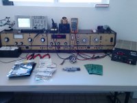
IMG_20140531_121245.jpg

Progress to date.
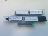
- Boards have been ordered and received they look fine and should work well.
- Brain chip and power control chip ordered and recieved from Lebowski
- Initial digikey orders placed for components had a bit of work to do to get everything itemized with qty and part numbers as you will see later I still missed some parts :)
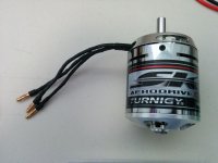
- Ordered and received a small BLDC motor as a test motor http://www.hobbyking.com/hobbyking/store/uh_viewItem.asp?idProduct=41051
- Currently going to use a 40 Vdc 5a bench power supply set at 37 Vdc (10S) ( for testing operating not sure how well it will go.
- Spent some time yesterday assembling the power supply only to find I forgot to order a replacement Inductor for L2 as digikey was out when I put the order in and since C51 had no part number I missed it also. Parts are on order and I should have them early next week.
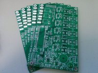
IMG_20140531_121253.jpg

IMG_20140531_121250.jpg

IMG_20140531_121307.jpg

IMG_20140531_121301.jpg

IMG_20140601_165417.jpg

Next steps:
- Finish board assemble and test RS232 communications for configuration
- Build output stage
- Test on small motor before moving on to IGBT/IPM.

Any Comments, Questions, Things I am missing :p

Cheers

Chris
 
Ok how do I make the image attachments show up as images not just links?? I tried the Img tags around the attachments but that did not seem to work :(

Cheers

Chris
 
purple_jeep said:
Ok how do I make the image attachments show up as images not just links?? I tried the Img tags around the attachments but that did not seem to work :(

Cheers

Chris
Hi Chris,

Reduce the image width to 800 pixels or less.
 
Miles said:
purple_jeep said:
Ok how do I make the image attachments show up as images not just links?? I tried the Img tags around the attachments but that did not seem to work :(

Cheers

Chris
Hi Chris,

Reduce the image width to 800 pixels or less.

Fixed thanks!
 
Well i received the missing inductor and capacitor from Digi-key and finished assembly of the power stage last night.

Since I am using a 40V (10S equivelent) bench supply for testing I calculated R_zen as:
R_zen = 660*(40 - 15)
R_zen = 16,500

Using this I could either use 15k or 18k so I used 18k.

Once R_zen was installed I connected the board to my 40V bench supply (5A capable) and turned on the power and..... nothing. Well D40 blinked on for a split second and then went out no voltage at the halls terminal or on the jumper so I must have missed something :(

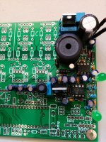
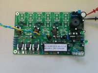
Anyone got any suggestions? I have double checked orientation of all capacitors and diodes etc also tried R-zen at 15k. Guess I will need to read all the resistor color codes tonight to see if I can find one I installed wrong. I have attached a picture in case someone can see an obvious error.

image.jpg
 
Which one is D40, the top or bottom LED ? After applying the 40V you have to wait for about 1 second before the supply is up.

The way the supply works, at startup it generates 5V_temp and 15V_temp with the 2 zenerdiodes. This is a very weak supply though, so what
happens is that the 12F617 at startup goes to sleep for about 0.5 to 1 second, allowing the weak 5V_temp and 15V_temp to charge the supply
capacitors (via normal diodes). So, first thing to check: measure the 5V_temp and 15V_temp to make sure they are there.
Once the 12F617 starts the first few pulses to the gates of the FETs come from the previously build up charge on the capacitors. Once the normal
15V and 5V are up they supply the power for the supply block (this is why the 5V for the 12F comes via diodes from the 5V_temp and 5V)

If all seems OK, can you try 60 or 80V ? (no need to change R_zen, it's a bit low but this just means there's more current wasted in the zeners)

P.S. make sure you didn't swap the FETs ! One is an NMOS, the other a PMOS so they are not interchangable.
 
D40 is the top LED. I waited a few mins and still nothing.

15V_temp is reading 20.75V
5V_temp is reading 0.05V

Something wrong with the 5V zener? might switch it out for a new one. Hope I didn't mix it up with one of the 1N4148 somehow

Cheers

Chris
 
yeah, strange, I mean, looking at the schematic you can see how the two zeners and the resistor work together to make a temporary 5V and 15V...
Maybe take out the two chip to remove the load on the 5V_temp and 15V_temp, and measure again ?

Maybe the 10V zener is not correct, it has 20V across it... if you substituted one accidentally for a normal diode, based on the measurements
I would say it's the 10V one

the 20V on the 15V_temp maybe comes from a small (via R_zen) current going into the supply pin of the gate driver. this chip is only rated for
20V or so, and maybe has a weak zener diode across the supply for protection...
 
Yeah I understand whats supposed to happen and I am also struggling to see why its not working. I will remove the two chips when I get home and see if that does anything.

Failing that I will remove both zener diodes and test them on some bread board or just replace them. Pity you can never read the numbers on diodes this small :)

Cheers

Chris
 
One more thing to keep in mind... the big 1.5mH inductor is sized for 150V, but since you're running such a low voltage, if you suspect later on the supply is not good you can put a second inductor in parallel as a test cause this might be the problem then. I never went lower than 65 V and i know all is ok at this voltage, but i never tried as low as 40...
 
I have another bench supply I can run up in voltage (0-300Vdc) but it is limited to 300mA will this be enough to power the power supply section as a test?

Cheers

Chris
 
purple_jeep said:
I have another bench supply I can run up in voltage (0-300Vdc) but it is limited to 300mA will this be enough to power the power supply section as a test?

Cheers

Chris
Yeah i think with the controller in full operation the supply current is about 80mA.

I think it is possible to supply the pcb with a different voltage as the output stage, just connect the grounds together.
 
Well I tried a higher voltage (100Vdc) no luck so I decided to have a look at the Zener Diodes. Removed the 5V zener checked its part number looks good, removed the 10 V zener checked its part number.... hmmm 1N4148 is not a zener diode!

Yup you were right the 10V zener was incorrectly placed for some reason I installed it at D43's location.

Once switched the system fired up with 40V no problem! Thanks for your help!

With power on the 5V signal at the hall connector was measured to be 4.788 Vdc so this resulted in a R_5V of 10k, the 15V supply was measured on the jumper to be 14.87 Vdc also resulting in a 10k R_15V.

After these resistors were installed the 5V supply ended up at 5.067 Vdc and the 15V supply at 14.87 Vdc.

Thats all I had time for tonight so I will leave you with a picture of some pretty LED's :D

image.jpg

Cheers

Chris
 
I'm happy the incorrect diode didn't cause the rest of the power supply to blow up :? I had a look at the IRS2186 (the gate driver) datasheet and it indeed has a 20V clamp in there, I think this saved it :D
 
Awesome project!
What kind of IPM are you intending to run? Maybe the Toyota ones like the Prius MG1 and MG2 or even the RX400H / Highlander MGR (like http://www.ebay.com/itm/321305632909) :shock:
I'll be sure to follow as these motors can be had quite cheap for the power, but are a hassle to drive.
Also see http://www.diyelectriccar.com/forums/showthread.php/toyota-ipm-motor-controller-design-details-87535.html.
 
Hi All,

Sorry for the long hiatus, I went to Germany for 2 weeks for a friends wedding and then have been working on my car since a piston decided to destroy itself :(.

But I am back :)

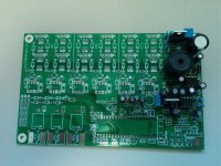
I finally received the last few missing parts (3 caps and two transistors) and completed the wiring on the board.

For R_mot I ended up with 3k value and for R_fo1 and R_fo2 I used 10k.

IMG_20140816_154830.jpg

After running to work to get a usb to serial adapter I connected to the board and on my first attempt I got nothing :(. Turns out I put the jumper on reset instead of setup whoops! Powered down and tried the jumper on the setup pins and success! Up came the menu!


Next is to build the 6 fet power stage and run a small motor to make sure I know whats going on. Then it will be time for a Power control module!

Few questions for Lebowski:
1.) Since I am testing with a bench supply can I turn off regen braking etc? Any other issues due to not using batteries?
2.) I saw in your thread you are concerned about running of low supply voltage. In my case I am using 40Vdc could this be an issue? You mentioned you had a different program for the power management IC for lower voltages?

Cheers

Chris
 
purple_jeep said:
Hi All,

I am fairly new to Electric Vehicle design and operation with brush less DC motors but I am an EE so hopefully I will pick it up fast but go easy on me as I get there :)

My brother (Bluefang) has asked me to build some Leowski style controllers http://www.endless-sphere.com/forums/viewtopic.php?f=30&t=57877 and see if we can get them running with IPM as an end goal for larger power applications (Hub monster been one of them).

My plan so far is to:
1.) Build a Lebowski controller with Lebowski output stage http://endless-sphere.com/forums/viewtopic.php?f=30&t=55641
2.) Using the same driver chips IRS2186 http://www.irf.com/product-info/datasheets/data/irs2186pbf.pdf drive IGBT modules similar to the Tesla Roadster Power module using the same layout as Lebowski's output stage liquid cooled if required
3.) Remove driver chips and drive an IPM using an external interface board for the Opto's etc required
4.) Modify Lebowski controller board to replace Driver chips with components required for IPM driving and mount board directly to IPM.

I hope to stay away from IGBT modules and their driving issues for high currents/voltages if at all possible by going straight to IPM's.

One thing I know may need some work will be the DC Link capacitor at these power levels but I should be good here as we are doing a project with the DOE at work on this very topic ;) So I will pick the bosses brain about what to use.

Chris

The IR2186 is not a very good driver choice for a motor drive, but will work OK in low power applications < 1KW. The reason it's not very good at higher power is it lacks basic features which make a gate drive more robust such as a Miller clamp or desaturation detection which can save the power devices from a shoot through / over current event. It would be worth your while to find a better driver when you decide to scale up, but for learning Lebowski's motor controller and getting the feel it should work just fine as Lebowksi has been using one for 1000's of kms, just don't try to ask it to perform tasks outside it's capabilities.

If you start going to higher power levels such as anything > 10kW you should use fully isolated gate driver configurations, this becomes more important if you will be going high voltage >100V. I personally use a TD350E driver in my projects because I have the most experience with it, but there are a few good choices for gate drivers available. The inductance of your motor will help determine the other parameters such as switching speed and DC Link cap size you need to design for. I like the gate drivers with fully integrated features, but those features come at the cost of propagation delay which will reduce you maximum switching frequency. I personally don't have much reason to switch > 30khz and that's about the max I can get a TD350E to go to (with 2 level turn off disabled) due to the propagation delay.

For a high end setup the Avego ACPL-333J looks like a good choice, but it's $5-7 each and you'll need 6, pricing isn't much of an issue for a few custom setups. Good news is that if the protection works even once, it will have pretty much paid for itself by stopping you from blowing up a MOSFET/IGBT and having to replace it or several.

For the DC Link capacitor, you can size them using the following formulas in the PDF I attached.
View attachment DC Link Capacitor Selection.pdf

I've been going over my gate driver design notes for the last few days and entering the information into OneNote which I'm using as my lab notes now. I think I have close to 50 pages of notes on gate driver design and layout and I haven't even started to add additional comments :shock: I'm trying to organize them into a general how to, but there is A LOT of information to cover; so much more than is found in the datasheets and app notes. The best source of information is from those experienced in this field which is how I learned.

As an EE gate driver and power stage design is skill set that could make you more marketable as well. I learned it because I was interested and knew it was challenging, I just didn't know how difficult it was and ended up taking about a year working on it weekly with a mentor. I've posted designs for gate drivers and power stages if you want to pick through them for info.
 
Zombiess, what a great PDF you made there.

When the inductance of the motor is unknown, can the measured value from a Lebowskis chip be used?
I did a calculation with the value my Lebowski chip calculated (5µH) and I end up with 50Arms. That's way too much for my selected capacitors.

Also, why do you use the minimum battery voltage when calculating? The calculated current ripple will be greater with a higher voltage like when the battery is fully charged.
 
Futterama said:
Zombiess, what a great PDF you made there.

When the inductance of the motor is unknown, can the measured value from a Lebowskis chip be used?
I did a calculation with the value my Lebowski chip calculated (5µH) and I end up with 50Arms. That's way too much for my selected capacitors.

Also, why do you use the minimum battery voltage when calculating? The calculated current ripple will be greater with a higher voltage like when the battery is fully charged.

PDF was created by HighHopes and posted a while ago, it's part of my notes on driver design. It's very useful so it's worth sharing.

The minimum battery voltage is used because when the battery is mostly discharged it has to work harder to keep the voltage and the current up. Think of how much a battery sags when it's almost discharged vs fully charged. The formulas targets a worst case scenario which means if you design for the worst case, your likely hood of success over all operating parameters is much higher.
 
purple_jeep said:
Few questions for Lebowski:
1.) Since I am testing with a bench supply can I turn off regen braking etc? Any other issues due to not using batteries?
2.) I saw in your thread you are concerned about running of low supply voltage. In my case I am using 40Vdc could this be an issue? You mentioned you had a different program for the power management IC for lower voltages?

Cheers

Chris

You can turn off regen braking by putting the max battery current, regen to 0.
40Vdc, it's on the border, if funny stuff happens it's too low, if everything works then it's fine :D
The issue is the mx dutycycle of the 12F617 DCDC converter. The supply times the dutycycle should
be higher than 15V, the max dutycycle is somewhere between 40% and 50%... I think reducing the 1.5mH inductor
would help, but that you can see the menu is an indication it'll be OK...
 
Hi Purple_Jeep
Did you finish the controller? Is it running? Are Bluefang and you happy?
It would be very kind of you to publish the complete BOM list with all the digikey part numbers here. Lebowski's original controller.csv contains the important parts, but not the little things as resistors and caps. This seems to be logical and easy for the specialists, but is a high obstacle for noobs. Digikey seems to have a tool which is able to convert a .csv or .xls into a complete order. So such a file (without needing KiCad) could be helpful for some of us (marcexec, beez65, ...).
Maybe somebody else did the same exercise as well and could contribute? Even if it covers only some of all the parts?
ThanX, emmgee
 
Hi Emmgee,

I will be back onto the controller this weekend, been a slow process due to LIFE :p

I have all the component part numbers except for the resistors (for those I suggest getting a set of standard values from Amazon http://www.amazon.com/gp/product/B003UC4FSS/ref=oh_aui_search_detailpage?ie=UTF8&psc=1 or similar)

I will put up a CSV tomorrow for you :)

Cheers

Chris
 
Back
Top