Lebowski controller build possible IPM output stage

I'll have a think about it when I get home, at the moment I'm in Taipei for a business trip...

The cutting out though is not normal and I suspect the power supply, can you scope the 5V and see whether it shows dips down when the motor spins fast ?
The controller IC has the brown out detection enabled, it will reset when the supply drops below 4.5V or so ... and a reset will look like a cut-out. I also
realized you won't seen this from the power supply LEDs, they will maybe glitch if you really pay attention but otherwise it'll seem as if they're continuously lit..
 
purple-jeep,
I am curious why you chose the IPM you did? A much better choice would have been the Power Semitech IKCM series with antiparallel diodes to allow faster switching.
Those parts are readily available. You could then have driven that directly from the uC and omitted all the gate drive stuff.
 
kenkad said:
purple-jeep,
I am curious why you chose the IPM you did? A much better choice would have been the Power Semitech IKCM series with antiparallel diodes to allow faster switching.
Those parts are readily available. You could then have driven that directly from the uC and omitted all the gate drive stuff.[/quote

All the gate drive circuitry is in the IPM the board on top is an interface board with optocouplers for the signal lines and isolated powersupplies.

Do you have a link to the IKCM a brief google does not find that company or that part?

I am using the one linked previously atm because it was cheap on Ebay more of a proof of concept part then one which will be used on an actual bike.

Cheers

Chris
 
purple-jeep,
The IKCM does not require optos on the signal lines or isolated supplies. Check out or get their App Motes.
Wanted to add: I would also recommend you checkout the Austria MicroSystems (AMS) AS5047D magnetic rotary encoder and use that as an SPI interface to the uC. I do not get this use of Halls because it takes too much overhead to deal with.
 
Lebowski said:
I'll have a think about it when I get home, at the moment I'm in Taipei for a business trip...

The cutting out though is not normal and I suspect the power supply, can you scope the 5V and see whether it shows dips down when the motor spins fast ?
The controller IC has the brown out detection enabled, it will reset when the supply drops below 4.5V or so ... and a reset will look like a cut-out. I also
realized you won't seen this from the power supply LEDs, they will maybe glitch if you really pay attention but otherwise it'll seem as if they're continuously lit..

Hi Lebowski not sure if you are home yet but any thoughts on the IPM interface?

Cheers

Chris
 
Any thoughts on the IPM interface.... not really. It all depends on what type of IPM module you want to use.

Some have standard 5v digital inputs, you can wire the PWM outputs of the controller Ic directly. Others have optical isolation, there
the inputs are the LED pins of the optical isolators. As far as the controller IC is concerned, its driving LEDs so you have to add
resistors and make sure the polarity is correct. If your module only contains the power devices without any driver circuitry
you'll have to build driver boards like Arlo1 is doing with his LEAF inverter...
 
Hi Lebowski,

I have built the reference interface board with opticouplers and isolated power supplies, you can see it on top of the IPM in the picture I posted earlier.

To drive the VLA606-01R (http://www.pwrx.com/pwrx/docs/VLA606-01R.pdf) it requires an on signal (IPM control input low) that is generated by pulling the respective control input low (GND) capable of sinking at least 16mA. In the off state the buffer should actively pull the control input high to maintain good noise immunity.

My question to you is as you currently have it designed if I set it to:

d) toggle high side polarity, now active LOW
e) toggle low side polarity, now active LOW

and connect the interface board to pins 1 for hi side and 2 for low side from the IRS2186 socket points on the circuit board will I be ok? Can the 30F4011 sink 20mA per input and does it pull the output high internally? These are 5V logic signals right? Or should I use a buffer?

Cheers

Chris
 
I think I need more info about the actual power module... I think the control inputs of the VLA606 are LEDs with series resistors, connected to 5V so they need to be pulled
down in order to light the LED and turn on the powerFET in the module... this would be logical as you want the powerFETs off when the LEDs are off.... imagine no power to the
controller IC, all LEDs off, turning on all powerFETs.... I would add a NPN transistor / 2 resistor combo to each controller IC output to drive the 20mA the LED needs. Have a look
at the RS232 circuit, I typically use 2.2kOhm from IC-pin to transistor base, with 680 Ohm between base and ground. This extra transistor acts as an inverter meaning you could
keep the controller IC active HIGH .

But, this depends on the module as the VLA606 spec only shows its input and output signals and not how this controls the power FETs.
 
You are pretty much right on the money with your comments!

In the application note for the interface board (http://www.pwrx.com/pwrx/docs/BP7B Application note.pdf it mentions to use a 74HC04 CMOS inverter to buffer the signal if required which would also work from the sounds of it. I think that's what I will do, connect the 74HC04 to the signals from your brain leaving them as active high and use that to drive the IPM.

IPM is a 600V 50A PM50RLA060 http://www.pwrx.com/pwrx/docs/pm50rla060.pdf for now as it was cheap on ebay for testing and that line goes up in voltage and current as needed.

I am off to Australia tomorrow to work with BlueFang on the actual motors and with batteries, built up a second board to the point of taking the measurements for the power supply resistors and will finish the rest of it on site. Will be there for about 10 days so forgive me if we come up with more questions :D.

Cheers

Chris
 
Well that was a fun few days.... kinda :)

First things first once I arrived here in Aus we had to get the 74HC04 CMOS inverter to buffer the signals from the brain board to the IPM and build a small prototype board to wire it up.

No problems with this and while working on it my brother (bluefang) worked on hooking up the HubMonster motor and the various battery packs (one for the brain board (50V), one for the motor (125 initially then down to 50V once we realised I had the brain set up for that), and one for the IPM interface board(24V). Also put a fuse in the motor battery pack line to prevent letting free the magic smoke (not so successful as you will see later).
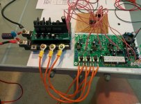
image.jpg

Once we had this all setup we went into the menu and started setting everything up, set the PWM freq to 15khz since the IPM is rated to 20khz. Set the current limits to 5 amp battery to match the fuse. Did the inductance measurement and the motor made a noise and gave a measurement of about 100uh so it seemed happy.

Once that was setup the moment of truth arrived and we tried driving the motor but as always nothing :p well we got a little bit of a twitch but no constant movement.

We tried both with and without the HF tone, when we enabled to HF tone we did the current sensor calibration and it seemed to work fine first one it made a noise second one it made a noise and moved a small distance. when not using the HF tone we set the current calibration back to defaults.

At this point we were going to switch to the newer 2.30 chip but I wanted to check as I remember something about the schematic changing from 2.10 to 2.30.

Played around with the erpm limits a little bit with no success and then found if I turned up the throttle quickly I could get the motor to start spinning and the drive 3 LED would light just for a few seconds and then the motor and LED would stop. Did this once or twice and blew the 5A fused we were using so thought good maybe we are too current limited. Replaced the 5amp fuse with a 25amp and changed the maximum battery current to 15amps to see if more power would help keep the motor going.

Alas at this point after trying the fast throttle trick a few times the motor started making a cogging noise even with no throttle so we disconnected and reconnected power to the controller thinking maybe it got stuck in a loop of some kind, no change still cogging with no throttle then the IPM blew :( 25A fuse was fine so I am thinking a current pulse must have done it since the IPM is rated at 50A.
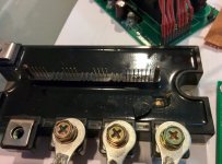
IMG_20150101_112318.jpg

Not the best end to the day.

Now looking to get a replacement IPM and see if Lebowski has any comments on what we did wrong and if we can switch to the 2.30 chip?

Cheers

Chris (and Derek/bluefang)
 
Do you think I can use super glue or should I go all out and use duct tape???

Cheers

Chris
 
I'm not familiar with these modules, do they have built in shoot through protection? It's easy to kill parts during shoot through events and during tuning/ testing on an older firmware I would occasionally fault with a shoot through error detected by my gate driver, but no damage.

Are all those wires gate drive signals going to the inverter chip? If so they are VERY prone to picking up noise. If they are gate drive, even digital, they need to be twisted to minimize loop area.

Bummer you lost the module.
 
zombiess said:
I'm not familiar with these modules, do they have built in shoot through protection? It's easy to kill parts during shoot through events and during tuning/ testing on an older firmware I would occasionally fault with a shoot through error detected by my gate driver, but no damage.

Are all those wires gate drive signals going to the inverter chip? If so they are VERY prone to picking up noise. If they are gate drive, even digital, they need to be twisted to minimize loop area.

Bummer you lost the module.

It does not look like these particular modules have shoot through protection, all they mention on the topic is a required dead time of >=2us which the controller has but now that I think of it I am wondering if noise in the control lines could have been the cause of a shoot through and thus a failure. I twisted the ones from the brain board to the buffer but not from the buffer to the IPM (made them up before I remembered and derek was in a rush to test). I knew I should have twisted them :(.

For fault protection the IPM monitors:
Faulty modes are classified into overheat, load (arm) short circuit, control power supply under voltage protection.

Also the module was used from Ebay so who knows what its life was prior to now.

Cheers

Chris
 
My bad on not taking a time out to twist the cables.

Well at least we learned that we can drive a IPM from lebowskis brain, pitty about the IPM not having a shoot thru protection setup. I guess we will have to find one that does as that is one of the things i want with these controllers. Safety features that mean i dont have to buy new ones all the time :) Hopefully we can find something in the same family of IGBT IPMs. I always thought IPMs would have that level of protection, half the reason i am so keen on doing a IPM controller.
 
[youtube]1WkOABO9HNA[/youtube]

This shows the actions of the hub running on the IPM, to me watching it makes me think one of the phases in the IPM was already faulty as the motors acting like its missing a phase.
 
I know, its difficult to resist the temptation to jump in fully and try to run a motor, but on an unknown setup its better to run a few checks first.
With unknown setup I mean the power stage you have, the one on the PCB is well known an will run good with the PWM settings provided in m the 'build your own' thread.

With a new setup, best is to start with the PWM test signal function from the PWM menu. Best is to have no motor connected (as this can mask problems) and
to have a current meter in the power line to the output stage. Start with a very high deadtime, look at the scope and current meter to make sure all outputs
are switching as they should, and that the current from the power supply is neglibile. Then you can slowly reduce deadtime (making sure the current doesnt
increase due to shootthrough). Make sure to measure all 3 outputs individually (a connected motor will short all 3 together, masking problems) and also
have a look at low (10%) and high (90%) dutycycles.

Second, I always make sure the current sensors are connected correctly. With a lab supply, or battery and car lamps, one after the other put a current through
the sensors and measure the voltage at the input of the controller Ic. Make sure the polarity is OK, that the sensor responds correctly when the current is
reversed and make sure the 0 current level is around the 5V supply midpoint (2.5V).

Its best to run these checks... what you describe with the throttle is not necessary, when you increase throttle the motor should just run. I recommend to try HF only
after everything works fine in sensorless, as the HF mode pust a lot more stress on the system. (Dependend on current sensor offset) the motor should run smooth
and without tendencies to lock at a certain point. You've tried it with the small motor, a big or small motor doesnt make any difference for this controller... big motors are
actually easier as their ratio of inertia versus cogging is much better.

This video is of a 10kW EnerTrac 602 motor. You can see the motor start smoothly (sensorless), without load and with a light load as I press my hand against
it. Both times I slowly increase the throttle....
[youtube]DsCLGBT2Dvs[/youtube]
 
Keep the twisted wires from the brain-buffer-IPM as short as possible, you can easily short 2/3 of their length.

Also, did you test the signals coming out from the buffer with a scope to see everything looks as expected? With prototype board like that, it is easy to forget a connection, even a supply connection to the 74HC04.
 
Yeah, looks like it will all be going back to the US with me as I have the equipment at home to do all these tests. Don't even have access to a scope easily here.

For the current sensor on the power line to the output stage does it need to be on a scope or is a fluke current clamp meter ok?

Quick question on shoot through, is that just both high and low side IGBT been on at the same time for the same phase? Why would this blow the 50A IGBT and not the 25A fuse? Wouldn't it be like short circuiting the output?

I will be twisting all drive wires and shorten them as appropriate.

Lebowski, for changing from 2.10 to 2.30 brain do we need to make any changes to the PCB?
Also eventually I know my brother wants to run higher than 150V for the battery (400V Vbatt, lower voltage for the brain board supply). There are a few notes on the circuit diagrams about the Vbatt and the resistor power ratings (1/4w for up to 150V I assume would have to go up in power rating to lower the battery sense voltage by so much?) can you comment on the other required changes? Rfo_1 and Rfo_2?

Eventual plan is to modify Lebowski's PCB layout to include the buffer chip at the minimum and possibly the entire IPM interface circuit and then have the board mount directly on top of the IGBT.

Cheers

Chris
 
Also the DC link capacitor was a bit warm at the end of the test once the IPM had failed.

Cheers

Chris
 
It kinda all looks like shootthrough in the output stage. Shootthrough is basically very high current spikes coming from the DC link capacitor, going through both a high and low side FET then back to the DC link capacitor.

Because the high spiked current path in local to the DC link cap and FETs, you're not seeing the high spikes in the (fused) line to the battery. There you just see the average current, which due to the spiky nature is much lower than the peak of the spikes the FETs and DC link cap see.

The DC link cap heats up based on the average I_rms^2 , this can be still quite high dependent on the spike amplitude. So yes, based on all this it makes sense that it was shoot through.

For the schematic of v2.30, have a look at
http://endless-sphere.com/forums/viewtopic.php?f=30&t=36602

As far as I remember, the changes are that the hall sensor pins have moved, and pin 6 has become a battery voltage sense pin. (don't remember which resistors are Rfo_1 and 2 ? what I would do,
keep the current the same so increase the resistors to reflect the change in voltage, then based on current and voltage calculate the wattage you need. Also, the v2.30 does not necessarily need
the voltage feedback from the motor terminals, but only when recovery is used and you understand the risks !)
 
Hi All,

Been a while but I am back in the US and my brother has the money saved up to give this another go, he ended up asking me to get a 200A 600V IPM http://www.pwrx.com/Product/PM200CL1A060 alas they are out of the control board so at this point I think I will edit Lebowski's board to remove the FET drive stage and incorporate the IPM drive stage based on the reference design from PowerEx.

This will mainly involve adding the 74HC04, one VLA606-01R opto-interface IC, three VLA106-24151 DC to DC converters and one VLA106-24154 DC to DC converter. Also to be added are some passive components and the 2mm single row bottom entry header receptacle for mounting directly to the IPM no wires to pickup noise here!

Lebowski, what would it take to have the 15V rail changed to a 24V rail as that is the voltage I will be needing to drive the IGBT's

Wish me Luck!!

Also plans for lots of testing following the guidance here in this thread!

Interestingly I was just reading some more information and the Short Circuit Protection is supposed to prevent shoot through damage so I am not sure what killed the first IPM.
6.4.5 Short Circuit Protection - If a load short circuit occurs or the system controller malfunctions causing a shoot through, the Intellimod™’s built in short circuit protection will prevent the IGBTs from being damaged. When the current, through the IGBT exceeds the short circuit trip level (SC), an immediate controlled shutdown is initiated and a fault output is generated. The same controlled shutdown techniques used in the over current protection are used to help control transient voltages during short circuit shut down. The short circuit protection provided by the Intellimod™ uses actual current measurement to detect dangerous conditions. This type of protection is faster and more reliable than conventional out-of-saturation protection schemes. Figure 6.17 is a timing diagram showing the operation of the short circuit protection.

Cheers

Chris
 
Back
Top