Lebowski controller build possible IPM output stage

Slowly working out how to use KiCad.

Lebowski how does this look as a modification to your power_supply sheet to generate the 24V I need for the IGBT driver chips?

View attachment Printing Print Schematic2.pdf

Next I am deleting the Driver sheets and adding a IGBTDrive sheet which means I will need to build new components and footprints, wish me luck!

In the processor block sheet you have phase_A, B and C as hierarchical labels but not connected to anything in the root but also as local labels in the same sheet, does kicad connect local and hierarchical labels?

Cheers

Chris
 
I cannot answer your KiCad question (it's been a while) but you have a problem in the schematic, around Q4.
This PMOS power transistor will not switch off as the source is at 24V and the gate can only go upto 15 (as this
is what the gate driver delivers in order to turn it off). So you will have an always conducting PMOS between the
24V and the 5V....
The source of the PMOS should be connected to the output of the 7815, providing this 7815 can deliver the
(roughly, should be less) 100 mA (wich equates to (24-15)*0.1 = almost 1W of dissipation in the 7815.) ...
 
Hi Lebowski,

Ahh yes silly mistake! Fixed that, when I do the board layout I will make sure to leave room for a heatsink on the 7815 if required.

I think I am done with the schematic (attached), figured out how to build new library components for the powerex parts.

I then annotated and generated the netlist. Then I wanted to run CvPCB to associate components and footprints but for some reason it is coming up empty with no associations for your parts and when I run Pcbnew from Eeschema it says no board exists for this project but when I run Pcbnew from the main Kicad it opens your board....

Very odd issues...

Cheers

Chris
 

Attachments

  • controller.pdf
    203.1 KB · Views: 100
Been a while but I have made some good progress, figured out the CvPCB issue, turns out if you have a cmp file you need to import it into Eeschema using the "Back import component footprint field" button on the tool bar as they have moved away from using .cmp files.

Also ran into the same issue with trying to associate your footprint library, had to add it to the library manager and set it as an old style library as its not in the .pretty format.

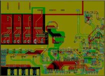
After all this I built the footprints for my new parts and started laying out the board replacing the FET drivers, had to make the board a little bigger to fit everything and I am sure if I redid the whole thing it could be simpler and nicer but I wanted to use Lebowski's as a base since this is my first time using Kicad.

Got it all done after a decent learning curve on the functionality of the software (filled areas etc etc). But for some strange reason 3 of my nets are showing as not connected even tho there is an obvious track linking the points... very odd...

Board.jpg

Any thoughts or comments? This board will mount directly on top of the IPM.

Cheers

Chris
 
I had the same problem with KiCad not seeing the connections. If I remember correctly kicad does not see a connection when you wire two paths together. So a half-length path coming from one component meeting up with a half-length path from another component does not get recognised as a connection. You have to draw an uninterrupted path from one pin to another...
 
I had the same problem on some component connections I just found it best to put a junction at all connections
 
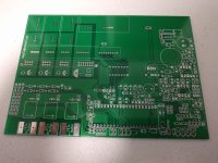
Well it has been a while but I have received the boards and finally had some time to look at it again!

IMG_20151209_185838.jpg

The board as recieved was fine except for two issues, somehow I managed to delete the mounting holes and forgot to add them back and also the holes for the IPM control chip were too small.

After buying a mini drill set I was able to fix the small holes and will just have to solder the component top and bottom of the board.

View attachment 1

Once this was done the board was assembled and the resistor values for 5V and 24V was determined.

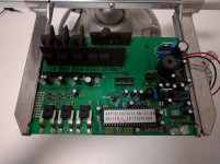
IMG_20151209_185113.jpg

Test fitting the unit on the IPM I will be using.


Cheers

Chris
 
After assembly I connected a cable to the RS232 port to run the setup and well nothing so far.... Not getting any communication over the serial port.

Any suggestions as to what I could be doing wrong or what could be wrong. I seem to have 5V on the appropriate pins on the Brain Chip (21,11,32,40) Enable is 4.45V is that right? Due to the diode drop across D46?

The other oddness which may or may not be related is that my 24V line drops to 17V when I have the brain chip connected. I am running off 48V maybe I need to flash the 12F617 for more stability?

Cheers

Chris
 
Probably the controller IC is not starting due to the weak 24V supply affecting also the 5V. What probably happens: controller IC starts -> 5V drops due to sudden current demand -> controller IC resets and waits for 64 milli-sec -> controller IC starts etc etc. The 5V takes quite some current from the 24V, so this then drops to 17V and makes the 5V unreliable.

You can probably solve all this by re-flashing the 12F617. You flashed this yourself ? I always assumed nobody really did this so I never updated the file for this one on ES. The 12F has a limit in a sense that the battery voltage divided by gate driver voltage (so in my case 65 / 15 , in your case 48 / 24) has to be higher than 3. The reason is a maximum dutycycle (of 33 %) that can be reached for switching on the NMOS in the gate drive voltage generation part.

You can change the maximum dutycycle (and as such be able to generate a higher gate drive supply) by changing this bit in the code of the 12F617:
Code:
								;if voltage still high enough, end
p20v_compare
    btfss CMCON0, COUT
    goto p20v_end
								;else turn on switch, pre-load timer, NMOS on
                                ;this value is 0xfc for the high voltage version (dutycycle max = 32 %, 9.5 usec high)
                                ;and 0xf9 for the low voltage version (dutycycle_max = 52 %, 15.6usec high)
    movlw 0xf9
    movwf TMR2	
    bsf GPIO, 0
    bsf myflags, in_deadtime_20V

Making this change in the code has no effect on the resistors so no need to change those.
If you decrease the 0xf9 to even lower then you can go to even lower input/output ratios, just be sure not to overdo it as this will cause an overvoltage spike on the 24V at startup.
 
Hi Lebowski,

Thanks for the reply, no I have not been programming the 12F617 but I have ordered a PicKit 3 to do this! 25% off on www.microchipdirect.com atm so thats good and overnight shipping!

I already have MPLAB installed from when I was looking at the code earlier so it should be straight forward.

Cheers

Chris
 
That IPM looks very familiar - PCM300CLA060?
 
I'm watching this with a vengeance then. That's the little brother of the Vectrix IGBT bridge.

Biggest issue will be getting enough bus capacitance with a low enough ESR - the original vectrix motorcontroller uses 4 X 47uf MLCC caps - unobtainum.
 
Guess what my day job is ;)

Managing a DOE funded project to develop next generation DC Link capacitors for automotive use. Current gen is all Metalized PP.

Cheers

Chris
 
Well you would be well and truly on top of this then! :p

There is another version of these IPM's as well - I've seen the 450A version on ebay for about the price you paid for the 200A. Different pinouts though.
 
purple_jeep said:
Guess what my day job is ;)

Managing a DOE funded project to develop next generation DC Link capacitors for automotive use. Current gen is all Metalized PP.

Cheers

Chris
Care to share any samples?
 
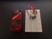
Well I recieved the PicKit 3 and made up the programming circuit on a breadboard, after changing the configuration settings so the PicKit would power the chip I was able to program the PIC no problem.

IMG_20151215_200401.jpg

After installing the new version with f9 instead of fc the 24V rail was stable so thats fixed. But I was still not able to communicate over RS232. After struggling with it for a while I discovered I had TX and RX wrong on my serial cable whoops!

Switched the wires around and up came the setup menu!! Tomorrow I will try sending PWM signals and checking them at the buffer chip socket prior to buffering them and sending them to the IPM drivers. Then the output of the drivers and finally connect the IPM with no load and check that also.

About the caps, Alas we are struggling to get enough samples to meet our DOE and industry partner obligations atm so we have a while to go before prime time.

Cheers

Chris
 
Since you've seen the amount of code in the 12F, just to compare, the code in the controller IC is spread out over around 50 to 70 files each like 5 pages of A4, all assembly..... (and compiles into around 40kB)
 
Hi All,

Slowly progress is made :)

So tonight I set the PWM parameters with a nice high dead time (need to reduce the PWM freq as the IPM datasheet calls out <=20kHz):
Code:
a) PWM frequency: 21kHz
b) deadtime: 4933ns
c) dutycycle testsignal: 50%
d) toggle high side polarity, now active HIGH
e) toggle low side polarity, now active HIGH
f) test PWM signals

g) autocomplete

h) loop sample frequency: 41.03 kHz

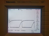
And first tested the PWM at the socket for the Hex Inverter/Buffer on the scope, all looked good (Lebowski does the chip drive all the outputs at the same time or should they be offset from one another? Looked like for example Wp, Up and Vp were on at the same time then after the dead time the n outputs would turn on together etc).

This was good nice square wave output then I installed the Hex Inverter and looked at its output, this also looked good just inverted of course :)

Then the moment of truth as I installed the jumper to activate the 24V to the IPM control chips and isolated power supplies (no IPM yet). No magic smoke yet!! Checked the power supplies, 24V was stable each of the 4 isolated 15V supplies read ~14.9V so they looked good. Fired up termite and started the PWM test signal and looked at the U signals.

IMG_20151216_193726.jpg

I think I see why I had a problem last time as I used the default setting of 500ns dead time. The IPM wants an on voltage of <1.5V and an off voltage of >2.0V. The output turns on in about 600ns and takes 500ns to turn off at those levels but the recommended are <0.8V for on and >9.0V for off which would take 800ns to turn on and 3,500ns to turn off! And these are all without the IPM connected. Will be checking that next to see if that makes much of a difference. Then with the IPM current loaded.

Girlfriend is calling me so that is it for tonight!

Cheers

Chris
 
Hi Chris,

During test mode the chip drives all outputs in phase... Nice to see you found the cause for the previous mishaps !

I think I see why I had a problem last time as I used the default setting of 500ns dead time.

actually, there is no default dead time (it does not autocomplete this part) as with all the different output stages people use there is just no predicting what is a reasonable value....

talking about default, the autocomplete value for the sample frequency has changed, now it is

f_sample [Hz] = (4/3) * (500 + f_pwm[hz])

so around 28.7 kHz for when f_pwm is 21 kHz. Not a big difference as far as performance or anything like
that goes, just according to signal processing theory this is more correct. (so: nerd stuff)
 
Hey Lebowski,

Sorry I didn't mean you specified a default I just copied the setting from the manual as a starting point but now I am looking at the traces etc it makes more sense to me what it is and why it would need to be adjusted for different switching methods.

I will use your formula to set the f_sample going forward instead of autocorrect :).

Just for future would it be possible to get a custom brain allowing me to tie in the fault signals from the IPM?

Cheers

Chris
 
The easiest way to deal with a fault signal is to just turn off the controller IC when a fault happens. When the controller IC is in reset it automatically turns off all the FETs and is completely inert. You can use a small processor to tie in multiple fault signals, add some flashing LEDs to display a fault code and one output tied to the reset of the controller IC. You can pass the power ready signal from the power supplies 12F through this small processor too....
 
Back
Top