
You are using an out of date browser. It may not display this or other websites correctly.
You should upgrade or use an alternative browser.
You should upgrade or use an alternative browser.
Miles' 90mm inrunner build thread
- Thread starter Miles
- Start date
Miles said:It looks to be the cubic root of the pole count ratio?
That fit's a bit better than the square root, on the true material numbers. But I think it's pretty arbitrary. When I was playing with the Colossus model, I got a ratio of about 1.15, at some point.
speedmd
10 MW
Hi Miles
Nice work on this motor. Thanks for sharing the details. I hope you get back to the axial design at some point. That design may have some significant benefit in a narrow design motor specific to ebike.
On your rotor design, have you considered the strength of the magnet ring/ hoop, and the effects of the magnets weights and pull/ resonance effecting how the hoop will keep its shape at higher RPMs. My gut feel is that you may need to significantly increase the width of that outer hoop wall just to keep its shape relatively round in use. If your cutting the lamination's with a laser/ water, you could add more spokes possibly to support a broader areas of the hoop to keep it thin the way you have it. Also, have you considered the v shaped extensions to the hoop to hold on the magnets as used on many. Looking like a Great project.
cheers
Hi speedmd,
Thanks for your thoughts.
I'll definitely have a go at the AF design, sometime. The ability to use grain-oriented steel should be a significant advantage, too.
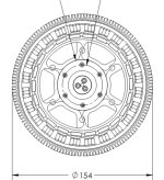
The rotor has been beefed up a bit with the change to 20 poles and the greater back-iron requirement. Maybe I need to look at this again, though. The mass of each magnet pole is 6.5 grams and the nominal speed is 3000 rpm.
I did consider using a dovetail fixing system but I found that it wasn't so good for a high pole count rotor, so I went with the slotted configuration. The original idea was to use rectangular magnets which could be used either way up but, with the wider magnets of 20p, I will probably use "breadloaf" pairs, so as not to have too much variation in airgap width.
Thanks for your thoughts.
I'll definitely have a go at the AF design, sometime. The ability to use grain-oriented steel should be a significant advantage, too.
The rotor has been beefed up a bit with the change to 20 poles and the greater back-iron requirement. Maybe I need to look at this again, though. The mass of each magnet pole is 6.5 grams and the nominal speed is 3000 rpm.
I did consider using a dovetail fixing system but I found that it wasn't so good for a high pole count rotor, so I went with the slotted configuration. The original idea was to use rectangular magnets which could be used either way up but, with the wider magnets of 20p, I will probably use "breadloaf" pairs, so as not to have too much variation in airgap width.
speedmd
10 MW
Hi Miles
Yes, the dovetails most likely best with much fewer magnets. It is a simple and secure way to hold them. This diameter/ 8 -10 pole size is relatively common stock magnets which does make it attractive for a lower pole count motor design. I just got production tooling quote to stamp 0.2 mm thick lamination's at near $4K. Ouch.
Axial has me thinking. Lots still to learn. Stampings /core lamination's can be more compact and used to makeup separate core / magnet assemblies which can be scaled up as needed.
cheers
New feature added to Emetor by special request of yours truly.
https://www.emetor.com/blog/post/release-2013-10-18-more-flexible-template-breadloaf-magnets/
Yet another parameter to tweak It also means that you can now, effectively, simulate rectangular magnets.
https://www.emetor.com/blog/post/release-2013-10-18-more-flexible-template-breadloaf-magnets/
Yet another parameter to tweak
It also means that you can now, effectively, simulate rectangular magnets.Just had a simulation session with the new feature.
Interesting result..... Nothing to be gained by decreasing the magnet radius relative to the airagap radius, in fact the best result was obtained by using a plain rectangular form (flat top)!
Interesting result..... Nothing to be gained by decreasing the magnet radius relative to the airagap radius, in fact the best result was obtained by using a plain rectangular form (flat top)!
John in CR
100 TW
Miles said:Just had a simulation session with the new feature.
Interesting result..... Nothing to be gained by decreasing the magnet radius relative to the airagap radius, in fact the best result was obtained by using a plain rectangular form (flat top)!
I'd need a plausible explanation before believing a simulation that tells me flat magnets are better in a motor.
So many different parameters interacting, sometimes quite sensitively...
In this case, better is only in relation to the shape of the back-emf waveform in an open circuit simulation.
Why should there be a prejudice against any particular magnet shape?
In this case, better is only in relation to the shape of the back-emf waveform in an open circuit simulation.
Why should there be a prejudice against any particular magnet shape?
John in CR
100 TW
If there's a prejudice mine would likely be in favor of the flat magnets since they're cheaper, and I rank economics so high. A constant air gap just "feels" more right. Flat magnets seem like flat spots on the wheel, though I guess it averages out across all the teeth on that phase with each a different relative position to a passing magnet at any given moment.
Assuming the simulation is correct, and the same goodness applies while powering it (sine controller I assume), then does flat ended stator teeth add even more benefit? Maybe you're onto something new. Could it be that the shape of the flux path is compromised with curved magnets?
The result is quite interesting, and I'm sure a lot of motor makers spend quite a lot extra on curved magnets, but without an explanation I'm left questioning the simulation.
Have you put any effort toward designing the bike you want to put it on? You must have some ideas already for a bike design worthy of your masterpiece of engineering art.
Well, as it happens, I do.John in CR said:Have you put any effort toward designing the bike you want to put it on? You must have some ideas already for a bike design worthy of your masterpiece of engineering art.
It's a folding bike.
speedmd
10 MW
Hi Miles
Great threads you have going on motors. Went back through some of the older ones and it got me thinking.
First off, I want a JOBY. No sense in trying to make something that does not come close when I have a complete motor bike to build around something like that gem. Now, what do I have to sell to get the cash.
Second, that design had me thinking a slinky style edge wound magnet core outer ring would be perfect. Quick search shows, I am not alone. Some stator cores made that way. Seriously cool.
cheers
Yes, there's some amazing stuff out there. Axial flux cores are often spiral wound from variable pitch strip.speedmd said:Second, that design had me thinking a slinky style edge wound magnet core outer ring would be perfect. Quick search shows, I am not alone. Some stator cores made that way. Seriously cool.
Here's an interesting paper: http://www.ee.kth.se/php/modules/publications/reports/2006/IR-EE-EME_2006_001.pdf
Are they still being made? I seem to remember a firm in China taking over production?speedmd said:First off, I want a JOBY. No sense in trying to make something that does not come close when I have a complete motor bike to build around something like that gem.
Brian is the one to talk to, here, about Joby: http://www.endless-sphere.com/forums/viewtopic.php?p=670083#p670083
The motor that Ryan designed for Zero is great value for the money:
http://www.zeromotorcycles.com/powertrains/powertrains-sales-sheets.pdf
Different scale to the Joby motors, though.
speedmd
10 MW
Hi Miles
The zero stuff looks nice, but way bigger and IMO not suitable for a light weight bicycle build. The Joby jms1 is the perfect size motor for a bb mount mid drive. Narrow/light/ventilated 150 cc size inrunner. If they don't make them anymore, someone else may have to make something similar .
Thanks for the links. Seems to me the only economical way to make lamination's with minimum waste of material as well as able to be done in a continuous manner. Great way to take advantage of magnetic /grain orientation also. You also should be able to make several different diameters/tooth counts from the same stamped roll. Will look up Brian.
cheers
The zero stuff looks nice, but way bigger and IMO not suitable for a light weight bicycle build. The Joby jms1 is the perfect size motor for a bb mount mid drive. Narrow/light/ventilated 150 cc size inrunner. If they don't make them anymore, someone else may have to make something similar
. Thanks for the links. Seems to me the only economical way to make lamination's with minimum waste of material as well as able to be done in a continuous manner. Great way to take advantage of magnetic /grain orientation also. You also should be able to make several different diameters/tooth counts from the same stamped roll. Will look up Brian.
cheers
Agreed. I wasn't sure exactly what you meant by "motor bike"speedmd said:The zero stuff looks nice, but way bigger and IMO not suitable for a light weight bicycle build.
Miles said:Are they still being made? I seem to remember a firm in China taking over production?speedmd said:First off, I want a JOBY. No sense in trying to make something that does not come close when I have a complete motor bike to build around something like that gem.
Brian is the one to talk to, here, about Joby: http://www.endless-sphere.com/forums/viewtopic.php?p=670083#p670083
The motor that Ryan designed for Zero is great value for the money:
http://www.zeromotorcycles.com/powertrains/powertrains-sales-sheets.pdf
Different scale to the Joby motors, though.
The Joby's appear to not be available any more, but if your real nice and patient with JoeBen..
theres a bigger jm on its way, but i tested the jm1s of brains pretty thoroughly by spinning it up from another machine and measuring the NM's of drag from 1 to 10k rpm, and a saturation curve for torque output to 400a.
perhaps i should update the motor comparison thread with some of this stuff, we have all the simulation data for it (and more for the less palatable ca120/collosus) so if we were to do a similar simulation for any of them as you have done here for the 90mm motor, we can then compare those results to the exact real world costs of producing rpm and torque from similar motors.
-stuff like the Watts used feeding 33khz pwm vs dc for making torque, (circuits) ripple currents at no load etc are all interesting variables that may not appear to even exist until you have one on the bench.
that would prolly help answer your earlier question miles, if there were any other variables.
i can tell from the rpm per volt and ir alone that this motor hits well above its weight, and the rpm losses are even more impressive, so im now dam curios.
That would be very interestingtoolman2 said:perhaps i should update the motor comparison thread with some of this stuff, we have all the simulation data for it (and more for the less palatable ca120/collosus) so if we were to do a similar simulation for any of them as you have done here for the 90mm motor, we can then compare those results to the exact real world costs of producing rpm and torque from similar motors.
We need to work out a standard procedure for simulation.
speedmd
10 MW
Got a note back from Scott at JOBY and the JM1S are a 4 week lead time. Thinking something in the 70- 80kv range. Looking more at the sizes, the slightly wider JM1 would fit also. Halls need to be added  Now, I am all confused. :?
Would love to see the data on them. High speed, light weight controllers a possibility? Does such a thing exist? If so, I can see a less than 35 pound cyclocross style bike (plus battery) build with this stuff. I wonder how that work on wheelie control is coming :lol: :lol:
Would love to see the data on them. High speed, light weight controllers a possibility? Does such a thing exist? If so, I can see a less than 35 pound cyclocross style bike (plus battery) build with this stuff.
Standard golden motor magic pie 2"s use a slinky style stator construction. Would the much superior (in one direction) grain oriented steel be any advantage using this kind of manufacturing method?
Very very good work with this motor Miles. Any idea of a rough time frame for construction, and basic stator cutting costs?
Zappy
Very very good work with this motor Miles. Any idea of a rough time frame for construction, and basic stator cutting costs?
Zappy
I'm not sure.zappy said:Would the much superior (in one direction) grain oriented steel be any advantage using this kind of manufacturing method?
Presumably, having the grain oriented across the strip would be the best direction.
Hopefully, I'll get something together this Winter. 30mm loose stator & rotor stacks will cost around $250 in 0,35mm M15 C5, I think. A lot more for Arnon7, I guess. I'm using 10mm long magnets as axial segments so stator lengths could be in multiples of 1cm.zappy said:Any idea of a rough time frame for construction, and basic stator cutting costs?
Similar threads
- Replies
- 7
- Views
- 556
- Replies
- 36
- Views
- 2,232