
Bearing brings his thoughts to bear on bearingsbearing said:a small change will have big bearing. (lol)
You are using an out of date browser. It may not display this or other websites correctly.
You should upgrade or use an alternative browser.
You should upgrade or use an alternative browser.
Miles' 90mm inrunner build thread
- Thread starter Miles
- Start date
speedmd
10 MW
Hi Honk
Interesting powder cores you used. Tell us more.
The bearing you used 6000 -zz was a permanent lube commercial grade? Tightly Grease filed? Tight Contact rubber seal? You went from a 26mm diameter bearing to a 8mm and 6mm oil bearing? I am not following how you can make a comparison, as the little bearing has a small fraction of the load rating and all of the grease filled ones need many hours to run in and become free and stable drag wise. Apples and oranges, with lemons mixed in.
Honk
100 W
- Joined
- Oct 10, 2011
- Messages
- 230
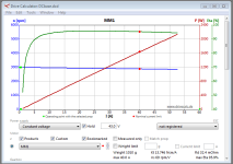
Great work Miles, 95,91% sounds really good and I'd like to see a video ASAP ones the motor is finished.... 
Meanwhile please catch up on powder cores by these threads.
http://www.rcgroups.com/forums/showthread.php?t=972859
http://www.rcgroups.com/forums/showthread.php?t=1348795
Btw, you miss the point.
The bearing swap was done to minimise all drag possible. Everything allowed!!
I wasn't comparing load ratings, lubrication or life time, apples or oranges.... 8)
There will soon come some more info on my progress....just hold on until I'm ready....speedmd said:Interesting powder cores you used. Tell us more.
Meanwhile please catch up on powder cores by these threads.
http://www.rcgroups.com/forums/showthread.php?t=972859
http://www.rcgroups.com/forums/showthread.php?t=1348795
Btw, you miss the point.
The bearing swap was done to minimise all drag possible. Everything allowed!!
I wasn't comparing load ratings, lubrication or life time, apples or oranges.... 8)
Thanks Honk.Honk said:Great work Miles, 95,91% sounds really good and I'd like to see a video ASAP ones the motor is finished....
Peak efficiency at 1100W output, it's also nice that it's still 88% efficient at 150W output.... Anyway, we'll see what actually manifests
Farfle
100 kW
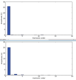
Pardon my noob-ness, but what does having a nicely sine shaped BEMF do for you? Does it just make it "match" to a sine wave controller and be slightly more efficient/less noisy?
Yes, that's the idea.Farfle said:Does it just make it "match" to a sine wave controller and be slightly more efficient/less noisy?
There has been discussion on the forum about what happens if you connect a motor in delta if it doesn't have sine EMF. It should cause recirculating currents in the windings. To prevent that, you should connect it in star.
On the other hand, I think that if you connect it in star, and use a 6-step controller, it is going to cause higher stator flux levels compared to sine control or 6-step delta, at the same torque, since you are only using 2/3 of the motor at a time.
On the other hand, I think that if you connect it in star, and use a 6-step controller, it is going to cause higher stator flux levels compared to sine control or 6-step delta, at the same torque, since you are only using 2/3 of the motor at a time.
Timely: https://www.emetor.com/blog/post/inductance-calculation-blac/bearing said:When running with sine AC, it also calculated the inductance.
emetor
100 µW
Miles said:Timely: https://www.emetor.com/blog/post/inductance-calculation-blac/bearing said:When running with sine AC, it also calculated the inductance.
Inductances should soon be calculated for BLDC simulations as well in Emetor. Star connection looks fine, but delta connection gives me some headaches :?
kenkad
100 W
Miles,
What would happen if you wired the 28/24 to be four three-phase groups? Does the Nm go up as a result? The I2R loss per phase would decrease since the phase R goes down. I am curious if your sim would show a slight increase in Nm? The inductance would decrease as well. Is the eddy current/hysteresis loss calculated? I did not see it shown or did I miss that somewhere in your data?
Still working on the 3D sim of the AF multi three-phase motor. We went to a 32/24 layout on the outer ring to maintain sine drive symmetry to all the three-phase groups. As I recall, when we tried 28/24, sine drive had to be skewed to each of the four three-phase groups. Current work is being done at a University so maybe soon we will have published results. Motor size is now about 125mm dia and 125mm long. At this point, I am just a bystander and letting the students have at it.
Kenkad
It's always changingHonk said:I noticed some differences in spec, have you changed the design?
You mean the value given for phase to phase resistance?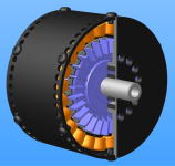

Beautiful work!
Nice motor , I'm waiting to see it in real life
(BTW wil be available to the pubblic? Price estimation? )
I know you are not a fan of finned motor but there is a trick to increase cooling without using space , is to thread the outer casting , the tread act like finn and almost double the surface of the motor ( metric ISO thread have a 60° angle so for every mm of base you have a 2mm air-metal surface)
I used the same trick when I was designing the new Guzzi motor ( http://www.bicilindrici.it/gmg/imgp1462.jpg ) the oil passage between the 2 exaust valve was unable to remove enough heat , so we treaded to increase the surface and the trik worked out.
Hi athlon,
It's not that I'm against adding fins, it's just that, for this application, there isn't room. There's 1 mm clearance between the motor case and the gearbox and that's needed for belt tension adjustments. The priority was maximising the airgap radius. I could do something like Ryan did with the Zero motor - shape the fins circumferentially to fit available space.
Threading is a neat trick for adding surface area. I'd thought about it for water cooling but not for air fins. I could thread the section over the core, that wouldn't make much difference to the strength and would be the most effective... hmmm.. Thanks for the thought.
You design ICE motors professionally, or as a hobby?
Similar threads
- Replies
- 7
- Views
- 556
- Replies
- 36
- Views
- 2,231