mounting hall sensors to R/C brushless motors

As soon as my new controllers arrive in the mail and I swap the FETs, I will be sticking hall's on my motors and giving it a try. I'm excited about it! I'm kinda into tinkering more than anything else, so i love any chance to work on something new.

Could you make a diagram to show us where to position the sensors for optimal performance?

Thanks!
-Luke
 
Sounds good Luke!

And, yes, if you guys want to do something with an encoder, I will machine the timing plate as well as hall mounting plate.

I just need decent sketches (assuming I have the machining capability to make what we need).

Matt
 
Not that I want anything to do with this project ( :roll: ) but they sell a lot of off the shelf encoder wheels.
I researched them when I designed my "completely autonomous three dimensional maze solving robot" back in the college days.
Usually clear with black lines so as to be easy to read with a breakbeam.

It is possible that we could even print some up on VuGraph material and glue that to lexan disks.
This would allow us to go custom.
Resolution can be sub-degree

-methods
 
That's a great idea Methy! I'm liking this project more and more :p You will also love spending hours of your freetime pulling your hair out trying to scratch together some code that works decent.

I've thought about it a lot, and I'm confident that with 6-phase control, we can double the torque of a normal 3-phase motor, vastly improve zero RPM torque, and I THINK the speed range would also double, though I'm not perfectly sure on that one yet. Efficiency would also improve. These are things that I find very attractive, and I would like to retrofit any motor with this type of control system so we can do some testing.

This is going to be very cool. If we make this work, I'm absolutely going to re-fit my dual motors with this sort of 6-wire control. I don't really care about the expense or time, I just want to do it.
 
Could you make a diagram to show us where to position the sensors for optimal performance
i kind of forget the pinout definition of the hall sensors, the three pins must be GND, VCC, and OUT

connect all three GND together and tie to controller ground
connect all three VCC together and tie to one of the 5V supply
OUTx are fed to the controller, but you'll need 3 pull-high resistors for this, b/c the hall sensors are tri-state output. if your controller has the built-in
pull-high resistors, which is valid for most controllers, you can save the pull-high resistors here.

the mounting positions of the sensors have to be spaced 120 deg from each other. the position is dependent on individual motors, for my HXT motor, each hall sensors have to be placed 4 slots away as i described in the previous post. i guess your turnigy motor is the same 12N14P motor, so the positions can be copied. i tweaked a bit on the mounting position to be 2 slots apart, to save space, but then i have to switch the polarity of the middle sensor, i.e. flip the sensor face.

btw, to find a good starting position for the 1st sensor, one easy way is to run the motor with a sensor-less controller first and move the hall sensor around the perimeter and find a spot that has the same switching position as the sensorless controller. OR you could do blind guess, in most cases, the sensors are mounted right in the middle of the slot or between slots.

since i could not open the motor to inspect the windings, i did not know which sensor output maps to which sensor input of the controller. so i tried all 6 combinations and find the one that works :? be careful not to fry your controller in this trial-n-error! i have a current limiting controller so it's totally fine for me :twisted:

to find the optimal timing, you could either try to fine tune the location of the sensors to increase the no-load speed or you can read the scope and see if the switching timing is right.

that should be it!
 
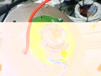
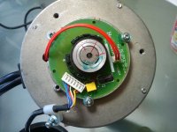
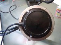
I decided to take apart my Cyclone motor
To my surprise, they have a very simple and eloquent way of picking up the phases
Those of you looking to try your hand at a conversion will probably want to look closely

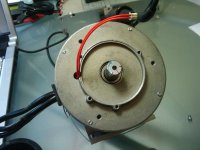
The motor shaft extends out of the rear of the case
There are two flats
The red wires you see are a temperature switch.... Nice touch
.
External_Sensors_002.jpg
.
.

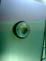
There is a ring that fits on the rear shaft and clocks to the two flats
I marked my parts just in case but it turns out that tightening down the worms almost perfectly lines everything up
.
External_Sensors_005.jpg
.
.

This ring above has magnets in it
The magnets are potted in the black plastic outer ring.
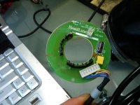
To sense the location of those magnets is this handy little board
Notice the multiple hall sensor slots that allow the end user to chose the timing
.
External_Sensors_001.jpg
.
.

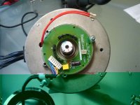
Put it all together and you have a very clever, adjustable way to sense motor position
.
External_Sensors_003.jpg
External_Sensors_007.jpg
External_Sensors_008.jpg
External_Sensors_010.jpg

btw: Those are Cell phone pictures *AFTER* being compressed with Irfanview. Amazing eh? Gotta love technology.

There are a pair of caps on the board for the hall sensors and the temperature switch is normally closed.

If anyone else has motors with different sensing methods it would be cool if you shared.

-methods
 
I don't really have anything to add right now, but I want to keep a watch on this. I have two companies making sensored outrunners for me, for RC use. Once I get them working, making a big one is easy. I have personally gone back to the dark side and like motors with hall effect sensors, but the controller needs to be hybrid so that it can switch over at low rpm and get max power or efficiency. Quite a bit more speed can be gotten out of a motor when the ESC can push the timing up to 45* advanced :mrgreen:
 
hi John,
do you have a number for the 45deg timing advance? how much no-load speed could you gain out of it? and what type of motor did you try?
i tried the small hacker style in-runner but no much gain tho....
 
It totally depends on the construction of the motor. The 45* advance is typically used on two pole inrunners in sensorless mode, it bursts a ton of power at expense to efficiency. High pole count motors may not see as much of a boost.
 
http://www.ece.wisc.edu/~lipo/2002pubs/2002_12.pdf

This is an excellent paper on 6 phase motor torque density increase vs. 3 phase
by Lyra and Lipo (yea, Lipo).

In summary, they claim a 40% improvement can be had. Not double, but still significant.
 
In the race engine world I come from, we battle hard for 1% improvements. If a 40% improvement in torque was on the table somewhere, we would do anything imaginable to achieve it.
 
This is an excellent paper on 6 phase motor torque density increase vs. 3 phase
by Lyra and Lipo

Didn't read the whole paper but I did see the two sets of three phases are only offset by 30 degrees, not 60 degrees, must be the trick to getting the efficiency increase.

I wonder if the effect may only work well with sine-wave drive, since there is a lot of talk of harmonics. May not be as helpful in the square-wave world. :?:
 
Yea, saying 40% is significant is probably an understatement.... :D

Take an HXT 80-100 @ 6 kw x 1.4 = 8.4 kW !!!! (assuming linear torque improvment)

In terms of the sine wave drive vs. pwm ....

I'd think that any harmonic issues would still be there and then some given
that you are hitting the coils with pulses....
How you'd go about compensating for them.... uhh... i dunno :?: :roll:
I wonder if you could still do sensor less control....?
 
From what I've read about going sinusoidal, is that you can generally pick-up about 3% efficiency improvement at the motor, which is of course nice. But it comes at a cost of 5-10% LESS efficiency at the controller, so you end up in a net efficiency loss. :(
 
That makes sense. If the harmonic content due to PWM goes up,
then efficiency could drop a little due to destructive interference?

What do we do with the idea of third harmonic current injection?

How would you go about pulling that off with a PWM controller?
Increase the duty cycle of the PWM signal (i.e. inject more current) modulated by the third
harmonic. Harmonic of what exactly? phase switching frequency? so, how
would you derive this signal. 3 x frequency in a micro?

I have to go back and reread that paper. :?

Ramble warning:

First of all, would just doing 6 phase control would be enough to start.
You guys with the dual motor setups are already running what I'd call a variant of a 6 phase drive.
You could probably phase them so that you get the 30 degree phase locked with timing chain/pulley
and drive it with a six phase drive. But you guys are running independent controllers right?
At first I thought that the controllers would be asynchronous in frequency, but
the motors are locked mechanically, therefore, in phase with each other with some random orientation.
The controllers are dependent on the frequency of the motors right? so the controllers should be locked
at the same mechanical frequency and resulting electrical frequency? But the phase difference is unknown.....
unless you guys are phasing the motors together like a overhead valve train on an ICE.

Ok, so why not split the stator (HXT 80-100, 12 pole -> 2 - 6 pole three phase) and run two controllers, one
per 6 pole three phase set.

The paper says the phase difference between the two "split-phase stators" is 30 degrees....That's the adjacent set
of windings (12 x 30 = 360) If my thinking isn't completely crazy, then it'll act like two independent motors right there in one stator just like you're running already with two motors in parallel!!!!!! that is crazy!!!! :twisted:
Now, you might get harmonic distortion and have it screw up the controllers or some effect on the feedback.
But I"m hoping for a loss in efficiency at most. :|
Maybe that is the whole point of this third harmonic injection craziness, etc..etc...etc...

But, hell, I'm gonna go order some more controllers!!!!! :mrgreen: This might help solve controller problems as well..
If you run 2 parallel 3 phase sets of windings at 80 amps per split....that's 160 amps total draw from batteries. YIkes.
Then off the shelf turnigy @ $100 dollars per split phase for $200 per motor would push 160 amp at 60-80% capacity for
reliability.

Ok, now, how do you wire it up? Do you run adjacent phases hot at the same time, or stagger them..

(end rant)

Hell, if this works, I'm changing my name from 12p3phPMDC to 2-6p3phPMDC!
 
I LOVE the idea, but the way the pairs split up in the windings, it's not as simple as that is it? I'm willing to help fund your testing if you have a gameplan to figure out how to make this idea work. I think it would be extremely valuable to both the RC comunity, as well as the E-bike guys.

Best Wishes,
-Luke
 
I'm sitting here with a Towerpro 5330 in bits (having just fitted new bearings - the ones it came with were stuck together with glue..........) and a pack of hall sensors. I'm pretty sure I can fit the sensors inside the motor easily enough, there seems room to epoxy them in place.

My question is:- What's the best place for them? Should the sensors be in the slots? In the centre of the poles? Somewhere in between?

I know that I have to fit them with the centre one inverted and with 60 degrees between the two outer ones (this is for a 12 pole piece motor), but I'm not sure what effect moving the whole sensor array around by a few degrees relative to the pole pieces would have. Presumably this advances or retards the motor timing, but how critical is this to performance and efficiency?

Thanks in anticipation to any here who can help!

Jeremy

PS: The baby 6 FET Infineon is now sporting a new set of IRFB3077 FETS (mounted on mica washers), good for 210 amps each peak, 120amps continuous, with an Rdson of just 3.3mohms max. They're only good for 75V, but that will suit me fine for the Towerpro, it will probably baulk at anything over about 60V anyway . The current plan is to use this to drive one of my Towerpro 5330s (fitted with hall sensors) as a test bed.

PPS: The bearings in these motors are truly crap, as is the quality control. Two out of the three bearings in the motor I've just taken apart were filled with glue and seized solid, but worst of all, none of the bearings had ANY lubricant at all! Nothing, no grease oil or whatever. I've just fitted some decent NSK bearings in and the motor feels really nice and smooth. I'd not even think of running one of these Chinese motors with the crap bearings they come with.
 
hi Jeremy,
maybe you've figured this out. in case you haven't:

sensors in the slots or at the middle of two lost? => i think this is really determined by the motor design, for my case, it's 12N14P and the sensors are at the middle of two slots. if you're totally unsure about this, you could use a sensorless controller to drive the motor and see where the sensors should be.

precision of the sensors location does not really matter initially, as long as the motor could self-start from zero rpm.


-george
 
What's everyone obsession with high voltage? You don't need high voltage to drive serious current through a 30 mOhm motor and with the proper gearing, you can get any amount of current(and thus power) to correspond to any speed thus getting the power curve over the speeds you want. With hub motors, which have a fixed gear ratio, it's true higher voltages are needed to increase the top speed but you're not limited to a fixed gear ratio with R/C motors.

But, it seems the current highest power limit is 50V*200 amps = 10 kW with RC controllers and I guess I can understand everyone's argument if that's inadequate for e-bikes. :lol:
 
mounting the sensors between slots is the easiest. If you want to have zero timing, then the sensor needs to be on the leading edge of the tooth. Having it in the slot is just fine and will give you a bit of advanced timing.


Just got word from the factory today that they are starting the prototype sensored outrunner for me. Once I can get one in my hand it can be tweaked and adapted to larger motors.
 
methods said:
They run at 24Mhz, are programmed in C++

lol. These things accept object oriented programming?

Of course, what am I saying. Object oriented programming can be implemented on any platform as they're just synchronized data structures in disguise and the eventual product is just 1s and 0s like any compilation, it just takes enough memory to justify object oriented programming.
 
Thanks very much for the advice, folks, it's very much appreciated. I was on the verge of connecting the motor up to a sensorless controller and moving a sensor around to see where it should go, using a 'scope, just as you suggest, George. There's enough room through the slots at the base of the motor to hold a hall sensor "probe" and move it from side to side across the end of a pole. It's a lot easier to fit the sensors into the slots as you suggest, John, as although they don't fit fully into the slot, they will locate accurately there and can easily be epoxied in place.

I may still drive the motor with an RC ESC to identify which winding goes with which sensor, and to check the timing. I'm really pleased to hear that absolute positioning isn't too critical.

The question about high voltage is interesting, as just looking at these RC motor specs you could easily decide that relatively low voltages are OK for high power. Looking at total system losses paints a different picture, though, as losses are proportional to the square of the current. Doubling the current gives four times the resistive power loss.

As an experiment, I'm going to try and see how efficient a relatively large motor (a Towerpro 5330-10t) will be when run from 36V but deliberately limited to about 600 watts maximum. In effect, the controller will never deliver full rated power (around 2800 watts max) to the motor and will be set up for a much lower maximum power (assuming I can get the Infineon PC interface to work). This is for an application that only needs an average power of around 70 watts (not a bike). The choice of motor was dictated by the desire to have as low a Kv as possible, to simplify a reduction drive. If a 600 watt motor with a Kv of around 200 - 250 was available I'd have gone for that, but it seems that motors in this power range tend to have much higher speed constants.

Thanks again for the advice.

Jeremy
 
OK, I've just been experimenting with one of my big outrunner motors, a standard (cheapo) 120 A RC ESC and a hall sensor, to try and see where the best place is to fit the sensors.

Fiddling around inside the motor is a pain, plus I found that there is quite a bit of jitter on the sensor output, presumably because it's a fairly dirty magnetic environment inside the motor. Interestingly, the sensors work very reliably up to about 1/4" or more away from the outside of the can. There's enough flux leakage near the end to switch the sensor nice and cleanly.

This means it will be really simple to make a nice, adjustable timing, hall sensor mount. All I need to do is make a disc that will pick up on the motor mounting holes, slot the holes in it so I can rotate it slightly to tweak the timing, and fit the sensors on stand-offs at exactly the right angular spacing.

Pictures will follow once I have it working.

If this works, then it makes for a really easy way to retro fit hall sensors to a motor. A really neat way to do this would be to have a cup-shaped CNC machined end cap to fit the drive end of the motor, with milled slots inside for the sensors. If I can find a suitably large diameter bit of alloy bar I may have a go at making something like this and see how it works,

Jeremy
 
Let's see the pics Jeremy! I'm working on doing the same thing, and I would love to see your pics. I will get some pics up myself in a few hours hopefully.
 
Sorry for the delay, I've spent a couple of hours this morning turning a bit of alloy bar into waste.............

Here's a picture of the unfinished basic alloy ring, it still needs the motor mounting hole slots cutting and also the Hall sensor slots in the outside:

3428877906_832254333f.jpg


and here's the ring loosely fitted to a 63mm diameter Towerpro motor, with a Hall sensor just resting pretty much where I need to cut the slots to hold them:

3428067475_aed3ed57d8.jpg


Before I go further, I need to double (and triple) check that the Halls are going to be in the right place..................................

The finished ring will also have some slots cut in to allow cooling air to flow through the motor, or I may just fit a port to one side to attach a small high pressure centrifugal blower, like the ones that fit into a PC slot for extra cooling

Jeremy
 
Back
Top