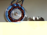
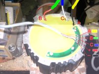
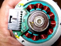
mounting hall sensors to R/C brushless motors

Jeremy,
is your Tower pro also 12N14P? that's weird, as my HXT is 12N14P too, then our hall sensor positions are quite different, 1/2 slot = off by 105 deg electric angle! hmmmm......i guess one of us is wrong on it, i'll go back and scope it to see the waveform again.
-george
 
George,

The Towerpro is definitely a 12 slot stator with 14 magnets in the rotor, and I have the Halls spaced at 120 (mechanical) degrees around the stator (one Hall in every fourth slot).

When I originally checked the Hall positions with the 'scope, whilst the motor was wired delta and being driven by the sensorless ESC, the Halls switched exactly at the zero crossing point of the trapezoidal phase voltage waveform.

When I checked again with the sensorless ESC, now that the motor is wired wye, I found that the Halls are now switching on one of the edges of the trapezoidal phase voltage waveform, an apparent phase shift of around 30 elecrical degrees or so.

The odd thing is that the Infineon doesn't seem to mind, it drives the motor just as well in wye as in delta, despite the apparent Hall phase difference. If anything, the controller might just be slightly smoother at low speeds with the motor in wye.

Jeremy
 
Guys, if I wanted to make my HXT 80-100-B power a moped (which I do, it's already mounted) ... would the Infineon you speak of do the trick?

I want to be able to take off from a dead stop, and if I can't figure out how to make a brushless motor do this, I'm going to throw my HXT out the window and shoehorn a brushed Etek in there and be done with it.

This thread is giving me some hope, I must say. I'm going back to re-read it all...

Luke, how fast will the Kelly spin an HXT?

And also, guys - what kind of voltage would an Infineon / HXT be happy with?
 
When I checked again with the sensorless ESC, now that the motor is wired wye, I found that the Halls are now switching on one of the edges of the trapezoidal phase voltage waveform, an apparent phase shift of around 30 elecrical degrees or so.
Jeremy,
that makes perfect sense! delta-wye switching should involve 30 deg sensor relocation.
for incorrect firing angle, in theory, there're two effects a. different no load speed (which i could not observe with my HXT, i heard it's very motor dependent)
and b. torque/A would be harmed if field is not 90 deg ahead of rotor. which would severely ruin the efficiency (again, i have no solid number to prove it yet)

i think i kind of know why my setting would work, i guess:
since there're gaps between magnets and the hall sensors would not switch until it sees the next different polarity (latching hall sensors assumed), so this introduced quite a lot of phase delay (this HXT looks like only 70% filled with magnets), plus i intentionally wanted the fire advanced angles.
 
Thanks for confirming what I've seen, George, that all makes good sense to me.

Mike, I wholeheartedly agree with George, you will be surprised at the massive improvement in low speed start-up torque when you fit Hall sensors to one of these motors.

Jeremy
 
Luke was ranting to me on the phone last night about shifting the phase of the hall sensors for the two modes.
Something about Markacycle doing some efficiency tests and discovering that he may need to run 2 sets of hall sensors.
I have not read the thread myself.

If one had a microprocessor, I suppose you could also calculate and inject the required delay.
This subject has not come up yet in the Delta\wye transmission thread but I suspect it will soon.
Once they agree that it works, someone will start doing efficiency test and discover the issue.


-methods
 
So, I opened up the new 6-wire 3210 I just received, to see about adding hall sensors. Here's what it looks like:

AF3210-12T-02.jpg


So, where is the best candidate spots?
 
Depends on the magnet. How many poles does that magnet have?
 
hi Miles,
the rotor/magnets is totally hidden. so there won't be a perfect spot that sees "direct flux". i guess the best chance is, place the sensors around the air gap and adjust the orientation of the sensors so that the sensors could see correct polarities from the leakage flux. as for the correct phase location, i guess using a sensorless controller plus a scope is the most precise method.

-george
 
Did anyone ever get to try hall sensors fitted to the outside of a outrunner ? ( I think Luke was the only one I seen pictures of) with what results. I am about to start playing around with a similar setup ( external fittment ) it would be so much easier to adjust the timing if they were on the out side but may not be worth the extra bulk with the fittment if the motor do not perform aswell as fitting the hall's internally. I think a sensored motor is the only way to go for me for what i what a bike to do, I have tried so many combinations and setups now using rc esc's that I am convinced that even a CC esc will struggle ( not that I have tried one ) so im go to save my money. I really need the instant/100% reliable startup from a standing start which a sensored motor will provide.

Cheers,
 
GGoodrum said:
So, I opened up the new 6-wire 3210 I just received, to see about adding hall sensors. Here's what it looks like:

So, where is the best candidate spots?

Hmm.... that motor has overlapping windings much like a Crystalyte. It might not be happy in the delta mode depending on the magnet configuration.
You might be able to test this by spinning the motor (maybe with a drill) and noting the torque drag with all the wires disconnected, then repeat the test with the wires in the delta configuration. If the drag remains the same, then you should be OK. You might be able to tell just by spinning it by hand. Any increase in drag is bad.

As far as hall sensor locations go, based on the Crystalyte configuration, you would locate them in the slots at two pole intervals. It doesn't matter which pole you choose to start at. It think it will work if you can jam the sensors into the slot behind the teeth. Even if you can't get them all the way in, I think it will work as long as they are as close. It's hard to tell exactly how big that thing is from the picture. If the space behind the teeth is not big enough for a hall sensor, it may be possible to grind away part of the teeth to make them fit (this is done in the Crystalyte and BMC motors).

You also might be able to get away with locating the halls so their flat face is almost touching the side of the rotor (covering where the red arrows are) to pick up the flux leakage from the end of the rotor. This would make it impossible to remove the rotor later if they were glued in. The gap beween the rotor and hall sensor needs to be small but enough so it can't rub.

To get real fancy, you might make a circuit board to hold them in place like a Kollmorgen motor. You could experiment by using some plain fiberglass or high temp sheet and just epoxy the halls and wires to the board. If you can the parts located with enough clearance, the cover will hold the board in place, making it possible to completely remove later. This may also allow for changing the timing advance.


AstroFlight_AF3210-12T-02 w halls.jpg

Kollmorgen hall and phase wires.jpg
 
I sure hope you are right Fechter.... I wish I had paid more attention in my Electromagnetism classes.....
I am really intimidated by placement. My self doubt soars... "Should I move it 1mm to the left :shock: ? 2mm to the right :shock: ???"

I called Bob to try to suggest the idea of gluing in the halls.
Got his helper - never got a call back.

I have no doubt that the technical solution to this problem is trivial in the right hands
The problem we really have is a human resources issue / personality issue.
If Bob decides to help us - we will be done - just like that (who is better too... He designed the motor)
If another member decides to solve the problem - we will also be done.

I will pay for the cost of building the first external hall board if someone will grease the skids and get Bob moving.
My only requirement is that the board work for both 3210 and 3220 motors so we can sell enough to offset some of the prototype cost.

If there is a member confident enough to glue in sensors and say for sure they are placed correctly I will drop-ship you a 3210/3220 and pay for the parts and time.

(and buy you an ice cream cone :mrgreen: Any flavor you want)

Can someone point me to the reading material I need to go through to systematically place sensors?
I dont even know where to start. . .
I have all the right tools - scopes, meters, etc. Just need the know-how.

-methods
 
Bob is supposed to call me back in fifteen minutes (11:45 am...), so when he comes back, I will ask him again why we can mount sensors directly to the slots, like the Clytes, and also I will ask him about the delta-wye switching, but I don't think this is a problem, or he would have said something before, and would have talked me out of bringing out all six wires.

-- Gary
 
I took a closer look at the Kollmorgen halls. The board holds them just above the pole teeth, facing toward the shaft. If there's enough clearance for a board to fit inside the motor housing, it might be possible to make a hall board to fit that motor. That would be much easier to assemble than gluing hall into the slots and trying to deal with a bunch of tiny wires.

Can ExpressPCB make circular boards?
 
Express PCB can make rectangular boards and we can cut them on a bandsaw.
May be cut them with a hole saw.

May not need to tho....

I just licked my finger and stuck it up in the air... I think.... I think.... yea... That is good news I feel coming our way :p

-methods
 
methods said:
Express PCB can make rectangular boards and we can cut them on a bandsaw.
May be cut them with a hole saw.

May not need to tho....

I just licked my finger and stuck it up in the air... I think.... I think.... yea... That is good news I feel coming our way :p

-methods

Actually, ExpressPCB can do round boards now, and you can define pretty much any shape that can be routed. You just need the latest software.

But, as my sticky-fingered friend alludes to, we probably won't have to resort to that. ;) I did finally talk to Bob this afternoon, and discussed the idea about putting the sensors in between the slots. It was like he suddenly had an epiphany, and decided, yes, it should work fine, either spaced every other slot, or every eight slots. Anyway, he's got a bunch of sensors, so he is going to try it right away. I had told him about this method before, but he obviously didn't comprehend what I was talking about, and kept going back to adding ring magnets and sensors on a PCB. No matter now, though. :roll:

Bob also verified that the 32-series motors have no problem doing delta-wye switching. He's tested this a number of times, most recently on a blimp that had a big 32" prop.

-- Gary
 
I would be a little hesitant to mount hall sensors with glue direct to the slots, as it would be hard to tune the position if there were some unanticipated flux distortion. On a board would be better, since it could be rotated slightly to tune.
If it is not possible to get a clean signal from hall sensors, we can always use optical sensors ( IR led/photo transistor pairs ) looking at a simple aluminum encoder 'chopper' disk. Not sure how much room there is in there, from the photos posted, and I don't have an Astro motor to look at yet.
 
Just like the clyte's, they will have trouble with delta-wye switching the moment they are running with sensors, as the sensors will be 30deg adv or retarded after the switch. Make sure he checks efficiency with the sensored controller after mounting sensors. My personal experience showed me just an 1/8th" of shifting my hall sensors would cause major motor heating.

I think the right way to do this is to make a board that is a nice snug fit into the back bearing cover of the motor, and on the board have 6 tiny surface mount hall sensors, along with a pair of 4-channel op-amps (only 3 would be used on each one) that output to trigger a set of 3 tiny output FETs. The shaft of the motor would have a loc-tite press fit thin little magnet ring made to pass over the board in the back. Then you would have the normal +-5v, sensA, sensB, sensC, along with a wire to activate the switching of sensor position for delta-wye switching. The board could normally be set to power the WYE mode, and when it that lead get's tied to gnd, it could pull down the voltage feeding the WYE op-amp, and switch a little PNP on to turn on the other op-amp reading off the WYE positioned hall sensors. All these parts, includeing the hall sensors could be surface mount, so the whole populated board thickness could be about 3-4mm, and a 6 lead JST connector could be mounted somewhere on the back, with a little slot milled in the end-plate of the motor to let it poke out.

That way, you could have correct sensor position for delta and wye, and only need 1 simple extra wire to trigger the sensor position swap. Total components cost would be <$10 Single sided board, dab the pads with solder paste from large bore needle syringe, place the components by tweezers, toss in the toaster oven, and poof! Sensor board. I bet they could be assembled by hand in 5-10mins each.
 
Yup.

p4140352large.jpg


p4140344large.jpg


p4140345large.jpg


p4140346large.jpg
 
GGoodrum said:
Bob also verified that the 32-series motors have no problem doing delta-wye switching. He's tested this a number of times, most recently on a blimp that had a big 32" prop.

-- Gary

That's good to know. Like I always say, one test.....

Stuffing them in the slots should be fine if they can fit. Dealing with the wires is a bit of a PITA, but if he's going to do it, no worries. A board might still be a nice thing for retrofitting existing motors.

I'm not sure if switching from delta to wye causes a timing change. It seems like the relative position of the magnets to the poles wouldn't be changing, so I'm not sure why the timing would change. It seems to work out fine on a 9C hub motor.

On a little Ametek inrunner motor, what they did was extend the rotor a bit so it's longer than the pole pieces so it can face directly to the hall sensors. I think a similar position would work with the AF motor, even with the stock rotor.
View attachment 1

Ametek hall sensors 2.jpg
 
Back
Top