Street legal Cafe Racer build.

PK2000

100 W
Joined
Oct 17, 2023
Messages
101
Location
Perth
Some background. I've been wanting to build an EV of some kind for a long time. Rapidly changing technology and a small number of reference builds (in the classes of vehicles that interest me) have made this feel risky.
About a year back, a guy I work with finished this WR250 conversion.

Doug freely admits that there was a lot of "Suck it and see" engineering involved but, it has to be said, he did a really good job on the bike. Every design decision he made ended up with a totally usable outcome and, looking at the bike, you can easily see what you would change and how much you would change it by to get a different kind of machine. In short it's a great bike and an excellent reference point for other builds.

I say it's a great bike, but to be sure, we put road tires on it and rode it to work and back for a week. The idea being to get past the novelty of a new bike and really measure currents and temperatures in my intended use case.

By the end of that week I wasn't shy with the throttle and the QS180 motor wasn't getting more than slightly warm at the end of the freeway leg of the trip delivering 10-12kW continuously. The battery pack was almost big enough for a weeks commuting and the fardriver 96V controller was holding up well. Like I said, it's a great bike!


OK, so now I'm feeling confident.
The plan is a cafe racer style bike.
411933426_6936623346451644_8428679629376531984_n.jpg
and I like the BMW R's because they have nice big cradle frames, single sided swingarms, and shaft drives...
Time to spend some money!
I bought a 1985 R80 mono,
asbought.png
for more $ than I should have spent.

Part of my intention with this project is show what kind of street legal bike can actually be built with the low cost EV hardware that's readilly available.
I rode this bike for a couple of weeks so that I would be able to compare it to the finished article. Sadly, this involved fixing a bunch of stuff.

I confess, at first, I was riding the bike and looking at the retro BMW guys thinking "What are you smoking, these things are crap!"

Then we put it on the dyno and the bike was producing 8kW at 100km/hr. Fixing the carbies got us up to respectable numbers and balancing them got the bike to a point where I was starting to second guess my decision to convert it!
dyno2.png
dyno.png
As with all dyno results the absolute numbers are irrelevant, although we checked the calibration of this one. What you see there is the R80 in blue, and some early test data from Doug's WR250 in red. At about this point, my nostalgic affection for the R80 faded.

So I sent off my application to modify the bike
This is a simple online form

And started ordering parts. We buy a lot of stuff out of China, so we're quite familiar with the process. With the exception of Harry, at QS motors who is excellent, the other vendors were disappointing.

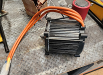
So I now have a motor:
motor.png
After getting stuffed around and enduring three or 4 vendors doing the bait and switch thing, I finally got hold of Fardriver and they agreed to make me a ND1081800B controller, though they want 2 months to build and ship it???

After only a month of stuffing around, I'm told that a box of Molicell P45B cells will ship today.

I've made some progress on the build, this'll do for an intro post.
 

Attachments

  • 1704335180297.png
    1704335180297.png
    210.4 KB · Views: 8
Fantastic, looking forward to the build.

Shaft drive? What's your plan there? Some fabrication required...
 
Fantastic, looking forward to the build.

Shaft drive? What's your plan there? Some fabrication required...
Yeah, it does require an output shaft to be lined up with a universal joint that is inline with the swingarm pivot, and it's gotta be pretty close too.
I decided on the engine mounts as the datums for the build and turned these:
tapered mounts.png
To locate in the mounting holes on the engine.
I lashed up a couple of supports, shimmed the whole thing level and took some measurements:
laser1.png

Then I put some M12 tapped holes in some 20mm plate.
plate1.png
(I'll install some lightness into it later)
and fitted it to the bike:
plate installed.png

Now I could check my measurements with a laser cut template:
laser template.png
aaaaand I was out by a bit. In my defense, nearly all of that error comes from the plate mounting a little off center in the frame.
Hmm. a buddy has a 3D scanner and has offered, maybe I should.
Time will tell. I'm confident enough to try a 3D print of a simplified gearbox case, just to see if everything lines up.

RevA.png

The first half of that is on the printer and has finished.
frontdone.png
So I'll print the other half tomorrow and see how far out I am.
 
Last edited:
Nice, are you making a gear reduction?
Did you order the cells from China too, what did you pay for them?
P45 has always been expensive when I have looked, like almost double of a p42 or samsung 40T
Yep, gear reduction, 25:43 (the final drive gearbox at the rear wheel is 10:32)
Yep, I bought the P45's from these guys: 1704369898075.png
See how we go I guess. I mentioned earlier that I'm not very impressed with a lot of the vendors in the EV space. Even these guys sent me a PI with the wrong bank account details. It took 3 weeks to get my money back.....
 
One of the side projects for this build is the instrumentation. I'll be building a body control module to talk to the BMS, motor controller and a few other things, but the gauge will be independant and just fed a serial data stream. I've mostly got it done:
 
Gearbox case print complete and it looks reasonably good.
caseinplace.png

I've test printed just about all I can and I reckon it's within a few shims and maybe an oversize mounting hole of right.
gears.png

So it's time to finish the gearbox design and start cutting metal.
 
One of the side projects for this build is the instrumentation. I'll be building a body control module to talk to the BMS, motor controller and a few other things, but the gauge will be independant and just fed a serial data stream. I've mostly got it done:
Did you program the LCD as well? Looks very good. I converted a 1972 honda (street legal as well) and kept the speedometer but used the bms display in lieu of the tach. Have since upgraded the BMS and am printing a custom case for the new display to accommodate the form/mount of the original Honda tach. The plan is eventually to sub this out with a custom display as well using the the bms serial feed. Interested in any detail you can share on that. Cheers
 
Did you program the LCD as well? Looks very good. I converted a 1972 honda (street legal as well) and kept the speedometer but used the bms display in lieu of the tach. Have since upgraded the BMS and am printing a custom case for the new display to accommodate the form/mount of the original Honda tach. The plan is eventually to sub this out with a custom display as well using the the bms serial feed. Interested in any detail you can share on that. Cheers
Yes, I programmed the display. It used this display Round RGB TTL TFT Display - 4" 720x720 .
Beware, the recommended driver board is VERY short on spare pins!

I had to make a separate board with an EEPROM (for storing odometer values), pulse shaping for the speedo signal, differential line receiver for the data from the body control module, and a separate micro to control the backlight intensity based on ambient light.

That enclosure is just a 3D print for test fitting. I'll machine one from metal when I have my head around how it's going to mount.
 
I saw the ”simple online form” you linked. It’s unreal. My honda was not subject to such rigorous scrutiny, as I am in the US and moreover it was processed as a historic vehicle which is more forgiving. You seem more than capable of the engineering demands but I can imagine that form alone has put more than a few hobbyists off of the idea. Great project, very rigorous.

edit: i thought you were keeping the trans but it was the replacement gearbox. more space for power
 
I will initially, simply because I can't cut helicals.

If I'm happy with everything, and it's too noisy, then I'll get some helicals made. The bearings are specced to handle the thrust from a 15 helix.
But noise is relative right? The existing gearbox is all spur gears. So we'll see, it might be simpler to implement velocity based volume on the bluetooth than pull it all apart and change the gears.
 
Have you decided on a voltage and a cell configuratio?
I've decided on what I would like. The controller will go to 128V max, so I have an aspirational goal of 27S 22P. This brings me in under my weight budget and the cells will easily fit in the nice big cradle frame. But I suspect that the reality of wiring the pack will drive the P count down.
 
Well, getting rid of the chain noice and getting spur gears instead..
It will be interesting to see how it turns out. Do you have to custom make the gears, are there no standard gears that fit?
:) I'm getting rid of engine noise!

I couldn't find any 20-25mm wide gears and, if I bought stock gears, I'd end up having to cut splines or weld them to a shaft. This way I can turn the shafts and gears as a single piece.

I've still got a female spline to cut to slip over the motor shaft, but it's only 6 tooth.
 
I saw the ”simple online form” you linked. It’s unreal. My honda was not subject to such rigorous scrutiny, as I am in the US and moreover it was processed as a historic vehicle which is more forgiving. You seem more than capable of the engineering demands but I can imagine that form alone has put more than a few hobbyists off of the idea. Great project, very rigorous.

edit: i thought you were keeping the trans but it was the replacement gearbox. more space for power
Yeah, if you live in the USA, Australia (in fact a lot of places) seem over regulated. But it's not quite that bad.

Basically, if anything bad ever happens here, some government minister is held accountable. A good example is deaths on the roads. When we have a bad year and a few extra people drink too much/drive stupid etc, the transport minister gets a grilling about what THEY are going to do to fix the problem. The end result of this is that everything is illegal, thus allowing the politicians to reflect blame back onto the community (where it belongs).

Why this is not so bad is, if nothing bad happens, then the authorities will very rarely take action.
In this specific case people modify motorbikes here about as much as they modify them anywhere. Almost no one gets 'approval' for these modifications. If you do a good job and don't make anything that's obviously dangerous, then, should you get pulled over, the police will check that you've paid your registration and send you on your way.

If you don't change an engine and need to re register the bike for some reason, then (in my experience) a government inspection consists of checking that the VIN number is stamped on the frame and matches the documentation, that your lights and brakes work, and that the exhaust isn't too loud. I've never had a bike inspected and they've ridden it.

The USA really is different in that its government was conceived more as the hired help than the agents of royalty/aristocracy/deity.
 
Last edited:
I've decided on what I would like. The controller will go to 128V max, so I have an aspirational goal of 27S 22P. This brings me in under my weight budget and the cells will easily fit in the nice big cradle frame. But I suspect that the reality of wiring the pack will drive the P count down.
You should do 28s if you can (28 x 4.2 max volt per cell = 117.6v, still under 128v controller max by a decent margin). Obviously if you're building it from scratch yourself, you get to pick whatever arrangement you want. Just that 28s is a nice even number, can be broken down into 2 14s 48v sections easily, can get repurposed as such when the modules reach the end of their life... those are my reasons for aiming for 28s on my next build. Another reason for myself is that I peruse BatteryHookup for used modules, and it'll be more likely that I'll find something in the 28s range, rather than an odd number. That may not hold as much weight with your build, I see the resources you've used so far and you probably have the budget for whatever new cells you want. Nothing wrong with 27s of course, just my two cents.
 
You should do 28s if you can (28 x 4.2 max volt per cell = 117.6v, still under 128v controller max by a decent margin). Obviously if you're building it from scratch yourself, you get to pick whatever arrangement you want. Just that 28s is a nice even number, can be broken down into 2 14s 48v sections easily, can get repurposed as such when the modules reach the end of their life... those are my reasons for aiming for 28s on my next build. Another reason for myself is that I peruse BatteryHookup for used modules, and it'll be more likely that I'll find something in the 28s range, rather than an odd number. That may not hold as much weight with your build, I see the resources you've used so far and you probably have the budget for whatever new cells you want. Nothing wrong with 27s of course, just my two cents.
I see your points. All of which make sense. I'm going to be scratch building this pack using new cells so, as you say, I can sort of do whatever I want. The catch always seems to be packaging and making sure there's enough copper between the series groups. My rationale for the numbers started with the pack in Dougs WR250, which is my reference point for this build. He used 24S17P and it was just about right. I'm aiming for 150km range (he gets just north of 100km) so I went to 22P (the Molicel 45B's have more capacity than the 43's). My next constraint is weight, which (and there's a fair bit of guestimation in this) limited me to 600cells.

I did a quick check this morning and there's plenty of room (I could get 800 cells into this frame if I needed to).
cells rev A.png
That's one slice of 27S17P.
From a cell connection point of view it's pretty nice, the main terminations come out at the top rear and there's only one spot that needs extra copper to get the mm^2 up. I'm going to make a foam mockup and I'm 100% sure I'm going to put it in the frame, look at it, have a drink, look at it some more and hack it up with a saw because it looks hideous.

It's going to be an iterative part of the build...
Anyhow, thanks for your thoughts, I hope I've explained how I came up with 27S22P.
 
I've decided on what I would like. The controller will go to 128V max, so I have an aspirational goal of 27S 22P. This brings me in under my weight budget and the cells will easily fit in the nice big cradle frame. But I suspect that the reality of wiring the pack will drive the P count down.
I’ve looked a little into bms in parallel arrangements but have found some disparity into what is recommended. You would have one BMS unit? And with each lead connected to a single cell in only one of the P or would the leads be split across the 27P somehow?
 
Back
Top