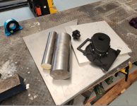
Street legal Cafe Racer build.

Each P group is effectively one cell as far as the BMS is concerned.
I see, so the P groups are in series, rather than the series in P groups. And so the individual cells in a P group will stay reasonable balanced to each other, or is that still a concern albeit minor?
 
I see, so the P groups are in series, rather than the series in P groups. And so the individual cells in a P group will stay reasonable balanced to each other, or is that still a concern albeit minor?
Cells in a P group don't have any option to unbalance, the instant one cell's voltage differs from any other cell in the group, large currents flow in or out of the cell to bring it into balance.
It might be a little hard to see at first, but if you look at the quick sketch I did of a simple pack layout on the previou page, you can see orange and green outlines. These will be large copper plates on the front and back of the pack (respectively) all the battery terminals within these outlines will be connected together.
Make sense?
 
I see, so the P groups are in series, rather than the series in P groups.

I'm not sure what you mean by that. P groups by definition means that the cells in them are directly paralleled, and so they are effectively one cell as far as their voltage, capacity, resistance, etc. The other stuff in series with them isn't relevant to their properties. ;)


And so the individual cells in a P group will stay reasonable balanced to each other, or is that still a concern albeit minor?
They will be identical in voltage (even if they individually have different capacities, resistances, etc) because paralleled voltage sources are always identical in voltage, when no current is flowing.

Now, if you used interconnects between them that are insufficient to handle the current flow at that moment, and the current from the cells in the group has to pass thru all their interconnects to get to the series interconnects to / from the other groups, *then* during that excessive current flow you would see differences in cell voltages because there is voltage drop across the resistance between them. But as soon as the current demand ceases, the cells within each parallel group re-equalize in voltage automatically thru their interconnects.

That's a different thing than a BMS balancer function, and not something you ever have to worry about--it's just how electricity works. ;)


Something to keep in mind about balancing though: All it means is the cells are equal in voltage throughout the pack, at one particular point in the charge curve (usually at the top of it, when full). Everywhere else in the charge/discharge curve, they will not be the same. Even when they are the same, it does *not* mean they are equal capability, or capacity, etc. For that, you have to use matched cells that are identical in all properties when you build the pack (not something you'll find in the majority of prebuilt "ebike" or "scooter" etc packs, just in large-EV packs), and even then as they age the cells will become different, and behave differently.

All balancing does is allow you to use more of the available capacity of a non-matched pack than you could otherwise, as an unbalanced pack gets moreso every cycle, so the less-charged cells get even less charge each time, lowering the available capacity of the pack to whatever the worst of them has.
 
Cells in a P group don't have any option to unbalance, the instant one cell's voltage differs from any other cell in the group, large currents flow in or out of the cell to bring it into balance.
It might be a little hard to see at first, but if you look at the quick sketch I did of a simple pack layout on the previou page, you can see orange and green outlines. These will be large copper plates on the front and back of the pack (respectively) all the battery terminals within these outlines will be connected together.
Make sense?
It does. You had labeled it 17p but now seeing the bus bars I understand it is 22p
 
Last edited:
I'm not sure what you mean by that. P groups by definition means that the cells in them are directly paralleled, and so they are effectively one cell as far as their voltage, capacity, resistance, etc. The other stuff in series with them isn't relevant to their properties. ;)
I was thinking 27s22p (27 serial groups of 22) vs 22p27s (22 parallel groups of 27). I can see now PK is doing the former.

They will be identical in voltage (even if they individually have different capacities, resistances, etc) because paralleled voltage sources are always identical in voltage, when no current is flowing.

Now, if you used interconnects between them that are insufficient to handle the current flow at that moment, and the current from the cells in the group has to pass thru all their interconnects to get to the series interconnects to / from the other groups, *then* during that excessive current flow you would see differences in cell voltages because there is voltage drop across the resistance between them. But as soon as the current demand ceases, the cells within each parallel group re-equalize in voltage automatically thru their interconnects.

That's a different thing than a BMS balancer function, and not something you ever have to worry about--it's just how electricity works. ;)


Something to keep in mind about balancing though: All it means is the cells are equal in voltage throughout the pack, at one particular point in the charge curve (usually at the top of it, when full). Everywhere else in the charge/discharge curve, they will not be the same. Even when they are the same, it does *not* mean they are equal capability, or capacity, etc. For that, you have to use matched cells that are identical in all properties when you build the pack (not something you'll find in the majority of prebuilt "ebike" or "scooter" etc packs, just in large-EV packs), and even then as they age the cells will become different, and behave differently.

All balancing does is allow you to use more of the available capacity of a non-matched pack than you could otherwise, as an unbalanced pack gets moreso every cycle, so the less-charged cells get even less charge each time, lowering the available capacity of the pack to whatever the worst of them has.
Thanks for elaborating. Will think more on this.
 
I was thinking 27s22p (27 serial groups of 22) vs 22p27s (22 parallel groups of 27). I can see now PK is doing the former.
The latter is potentially problematic for various reasons (true of all configurations, though), but especially because a failed cell probably won't result in just a shutdown system (assuming a BMS doing it's job), but possibly a fire during charging***.

If a cell in one series string (vs parallel group) fails in a way that results in an internal low resistance (short), it will drop the voltage of the entire string by that much. Then all the paralled strings will begin pouring their energy into it, while charging continues because there's nothing to shut it down***, and the failed cell heats from it's failure and hte continued energy flowing into it. In a pack that big, charging current could be fairly high...and essentially all of it would then be flowing thru this single failed cell....

Using the former system, at worst the paralleled cells in that group drain into the failed one; if it drops in voltage enough the BMS will shut off the input as if it were overdischarged. If current doesn't shut off, at least it's still flowing thru all the cells and not *just* that one (depending on the pack design and the actual failure). If the BMS has a temperature sensor it would (could depending on placement) detect the overheating cell and turn off input current.


There's no guarantees but there should be a better chance of catching and preventing a problem with the "usual" way of doing it.

***since a typical BMS can't be used in a typical way on a pack designed this way; you would have to either custom-make a BMS design for it, or use one BMS per series string that control a common contactor for charging input, where that contactor is *only* enabled if *all* BMS are "on" and error-free.


There is an advantage to the former way, in that if you *do* use independently monitored and controlled strings, you can't have a high-resistance failed cell drain down all the others in parallel with it--you just get one string disabled and not contributing to the load. As long as the pack is built heavily enough to handle the load with less than full contributors, or you have a system to advise you there's a problme so you can decide to stop, or the aforementioned full-system contactor that shuts off if any BMS turns off, you should be ok.
 
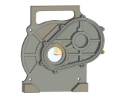
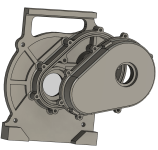
Half the gearbox case design done.
gearbox front Rev A.png

I'm waiting on some longer 10mm bullnose cutters, so I've got time to tinker with it some more if needs be.

Edit: Of course the moment I posted this, I spot some things I've missed..
 
Last edited:
You have a 1081800 controller specally made to be able to run lower voltage than the avalible 961800 does without problems?
The 96v line takes 28s fully charged
Far driver list the 961800 as rated to 115V, 28S would be slightly over that, but 27S just squeezes in.

I picked the 108 series because they use twice as many FETS in those controllers.

I design electronics for a living and have learned the value of voltage and current safety margins in power switching circuits. Particularly those with inductive loads.

You pay a price for it though, that 1081800B cost USD2K CIF!

I'd look at the 3shul CL1400 or even the Tronic X54 which uses TOLT mosfets - First of it's kind (speaking about the whole new X lineup from tronic)
 
I'd look at the 3shul CL1400 or even the Tronic X54 which uses TOLT mosfets - First of it's kind (speaking about the whole new X lineup from tronic)
And that would be a good option if I was looking to the cutting edge for this project. Don't get me wrong, there's certainly merit in those kinds of projects, just look at Chris' race bike as a great example.

If I were to take that approach on this build, I'd be looking to run a 300+VDC pack.

What I am trying to do here is take Dougs WR250 as a reference point and make small changes to get a robust, well engineered, and reliable bike based on the 100(ish)V technology that is cheap, well proven, and available.
 
That looks like a very interesting project so far.
The bike is a good choice, with plenty of space in the frame, great potential and lots of possibilities.
You seem to have all the necessary tools and skillset to see it though, good luck !

I wouldn't be bothered with the straight gears, it's too early to tell if they will or won't be noisy. My old Honda Hawk uses straight gears for all the gearbox and you can't really hear it at all.
 
I wouldn't be bothered with the straight gears, it's too early to tell if they will or won't be noisy. My old Honda Hawk uses straight gears for all the gearbox and you can't really hear it at all.
Thanks for the kind words. Yeah, these projects are challenging in as much as there are so many things to consider. The issue of gear noise is one (of many) that I'm addressing by ignoring it...
 
I finished the gearbox design and did a final test print. I've added a few mm to the base just in case I'm a little off in my measurements.
gearbox rev A.png

I'm waiting on some cutters to arrive before I make swarf on the case. I should get the case hardening steel for the gears today, so I can get stuck into those.

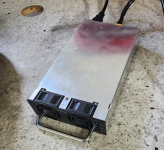
The on board charger arrived
charger.png
It's going to get some work to rewind it to whatever voltage I actually end up at, and to ruggedise it in the hopes of it surviving on the bike. Only 1.5KW but nice and small. Experience with Dougs bike says it'll be just about right.

There's lots of other stuff going on, but it's mostly non EV tasks associated with restoring a 38 year old vehicle. Not sure how much of that y'all want to see. Lots of sandblasting and painting and replacing worn parts. I gave up just fixing the obvious things and ordered every bearing and every seal.

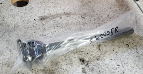
I had to buy an exchange driveshaft (they're not easily rebuildable)
new drive shaft.png


A big part of the difference between a perfectly functional and 'wow' on restomod projects is part finishes.
I already have an anodising set up for the aluminium parts, I can do electroless nickel and I do have some nickel cathodes (although I've not used them yet), and I have a selenium (gun blue) black tank. But a lot of the parts on 80's bikes were either bright zinc, or what we call cadmium plated. I kinda like the look of the gold cad plated fasteners so I grabbed Caswells copy cad setup with a few extras.
plating kit.png

Caswell kits are a bit pricey, but they include some of the things that are harder to source (like the brightener chemicals) and they've worked everything out and documented it well.


I've got a few weeks of travel coming up a the end of the month, I'll try to make some progress before then.

Oh, in other news, Jack from Far-driver is now saying that they can't deliver the 1081800B until AT LEAST March! Reading between the lines, it's clear that these drives are hard to get because they've had problems with them. It might be wise to have a plan B. I kinda like the VESC architecture because you can modify it. Anyone know if there's a reliable VESC based drive that'll do 650 battery amps at 120V?
 
The on board charger arrived
View attachment 345817
It's going to get some work to rewind it to whatever voltage I actually end up at, and to ruggedise it in the hopes of it surviving on the bike.
"Rewind it?" If it's a typical SMPS, rewinding it's transformers might not do what you want, because of the electronics being designed to create a certain output and hold it there.

And you also have to stay within the limits of all the other components on it, so you would probably not be able to go much higher in voltage than whatever it already is, and how much lower you can go would depend on the safety features it has for autoshutdown, etc and how bypassable or alterable those are.
I understand where your advice is coming from, so thank you. I certainly wouldn't advise anyone to rewind an SMPS.

Recall that I'm an electronics engineer and that my business designs and manufactures industrial controls.
I'm quite happy to pull that sucker apart and redesign the whole secondary side.

Those supplies are actually repurposed server PSU's that have been rewound and repurposed. They're really not that complex.
 
I didn't realize you were an engineer; almost no one that suggests alterations to things like these actually realizes what's involved.... ;)

(including myself, sometimes, such as the AI stuff I'd like to do with my Snuggles The Wolf robotics project, that requires the AI to "operate" or be "built" in a different way than they apparently are...but I have yet to learn enough about them to know any of that yet :oops:).
 
I understand where your advice is coming from, so thank you. I certainly wouldn't advise anyone to rewind an SMPS.

Recall that I'm an electronics engineer and that my business designs and manufactures industrial controls.
I'm quite happy to pull that sucker apart and redesign the whole secondary side.

Those supplies are actually repurposed server PSU's that have been rewound and repurposed. They're really not that complex.
Ok, I'll bite. Why are you rewinding/rebuilding a PsU as a charger, rather than just purchasing an available one already configured for the output you need? Is it cost?

Everything's relative; I can manually rewind a motor for better performance, but I probably won't. I can build a battery that I trust better than one premade, and I will/do. Everyone has their skills. I'm just curious about why you're basically building your charger rather than purchasing it ready made
 
I didn't realize you were an engineer; almost no one that suggests alterations to things like these actually realizes what's involved.... ;)

(including myself, sometimes, such as the AI stuff I'd like to do with my Snuggles The Wolf robotics project, that requires the AI to "operate" or be "built" in a different way than they apparently are...but I have yet to learn enough about them to know any of that yet :oops:).
Again, kind words. I'm staggering through the detail of this project. It was overwhelming at the beginning. Well, I put off even contemplating it before I saw Dougs WR250 and got some points of reference. It may still go horribly wrong. :)
 
Ok, I'll bite. Why are you rewinding/rebuilding a PsU as a charger, rather than just purchasing an available one already configured for the output you need? Is it cost?

Everything's relative; I can manually rewind a motor for better performance, but I probably won't. I can build a battery that I trust better than one premade, and I will/do. Everyone has their skills. I'm just curious about why you're basically building your charger rather than purchasing it ready made
Not cost, form factor and lead time.
1.These supplies are smaller than anything I can find that will do 113.4V.

2. I'm not even 100% that that will be the actual voltage, I'm yet to actually finalise the dimensions of the battery box and, in light of recent developments, I may be switching to a different drive. Just buying something I know will work (Doug has one of these) and rewinding it allows me to make that purchase now rather than at the end. My hope is that this carves some time out of the project. I'm doing this for a lot of aspects of the build and I know that I'll end up with surplus parts, but I'm happy to trade $ for saved days.

When the time comes, I'll measure the time it takes to mod the supply. Not that your time is something you account for on these projects. The work is the reward after all.
 
Last edited:
Again, kind words. I'm staggering through the detail of this project. It was overwhelming at the beginning. Well, I put off even contemplating it before I saw Dougs WR250 and got some points of reference. It may still go horribly wrong. :)
Yes, I know how you feel: I may create the first Terminator (guess it'd be a Wolfinator) by accident. :lol:

I've been "working" on this project for a very long time, but only recently has it really become possible to do for an individual like me (sort of, more or less)...and I am still nearly completely overwhelmed by almost every aspect of it, even though it is already completely built...inside my brain. :roll:
 
Hmm, so the guys at 3SHUL are quoting 30 days lead time for a CL1400. Far-driver are saying end of March .... maybe.
What would you do?
 
I kinda like the VESC architecture because you can modify it. Anyone know if there's a reliable VESC based drive that'll do 650 battery amps at 120V?
I only know of 3shul:s cl1400 that will do that, I dont know if I can say if it is reliable though. (They are supposed to release a 2400 too if I remember correctly)

Edit, didnt see that last responce when I wrote?
I like the programability and throttle control on the cl1400 a lot better than fardriver. It is not as snappy though when both are in linear and fastest response time. (there are more settings in the vesc that might be able to change that) So far 3shul has not held a dedline for me I think, and the build quility is not impressive.
I would still go with the 3shul, but maybe not on a street bike? Im thinking precise throttle control is less important, but you might want the more agressive response.
 
Last edited:
Back
Top