d8veh said:
Your estimates of speeds in each gear don't look right to me. I posted the actual no load speeds somewhere. With a 36v battery and 26" wheels, it does about 12mph in low gear and 20mph in high gear on the road. That equates to approximately 160 rpm and 270 rpm on the road.
Hmmm, since your the original "discoverer" of this motor I hate to contradict in any way but aren't those your 44v pack numbers not your 36v pack numbers? Or at least that's way I thought from your original thread on the UK forum.
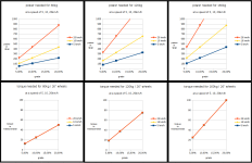
I mainly took the "Wheel RPM vs. Voltage" numbers off of the motor test table image at the bottom of this alibaba.com listing:
http://www.alibaba.com/product-detail/Double-Speed-Motor-Electric-Bike-Conversion_1195155734.html
Which I should note they seemed to have used an EXACTLY 36v (+/-0.02v tolerance) stable power supply for that test and it is notable that most "36v" e-bike batteries usually pump out a bit more then just 36v at least for the top half or more of their capacity.
If the motor is wound a little faster then that table indicates then that is good to know although if I've got the gearing ratios correct even with your faster RPM numbers for 36v its still only about 13,000 electronic RPM at 36v so I should be able to at least take the voltage all the way up to the 72v level without having issues with the 40,000 electronic RPM limit the controller I'm looking to use is limited too.
So do I at least have the mechanical gearing ratios correct even if the wheel RPM for voltage numbers are a little too low? Just trying to confirm the gearing works the way I think it does and those are the correct gear reduction ratios.