Lishui "Open Source Firmware" project / KingMeter 5S

Maybe easier to push brake and full throttle so the identification starts? But the controller I'm testing doesn't have BK pin. Just EBS, will it work? Also just hall sensor connector on TA pin, but throttle will work on that right? Or TB?

When I set auto identify debug in Java tool I still have to edit some code so it works?

Thank you
 
honya96 said:
Maybe easier to push brake and full throttle so the identification starts?
?! You write that you don't have a throttle and no brake lever switch, how should it work then???
The throttle signal has to be on pin SP and the brake signal has to be on pin BKL.

I don't know your setup,I don't know your expectation, what the controller should do :?: , so i can't say what you have to set in the Java tool :!: ....

regards
stancecoke
 
Success!

I found controller with brake wire, soldered throttle to SP and the detection started, also it's pretty fast.

(I thought the detection will start itself when I set detection in Java tool, but it doesn't)

Brake icon shows on kunteng display, power, throttle, but battery doesn't show on lcd8, whatever I set in Java tool. Even when set 1 for 1 bar, it shows no bars.

Will test on lcd5 which I need it for the most.

I have a pile of sensorless "F" controllers. So I think I'm now able to add sensor connector and use them sensored. And also with cheap kunteng display.

I will try to update wiki when I have time. Thank you for your help.

Also I wonder, do the settings on KT display do anything? Can motor temperature be showed when I add sensor wire to the correct pin?
 
I started a thread about my problem with 2 same lishui controllers, not related to this at all, but I will put link here if anyone has any idea what's wrong. I'm just curious to find out because it looks like a common problem with this model number

 
@stancecoke can you please point me where to change linear brake min and max voltage? im now testing on a scooter which needs regen and i have 0.9v on the brake not pressed and 3.4 when pressed all the way, so its still braking.

and theres a little problem at low speed it has low power and then stutters when switching to FOC, then its accelerating much better. I lowered the rpm to switch to 2500 which helped, but its still not ok
 
can you please point me where to change linear brake min and max voltage?
You have to hardcode the values directly in the code, if the min/max values are different from the throttle:
https://github.com/EBiCS/EBiCS_Firm...100e1d15ad04c45277ff78fe1bd29/Src/main.c#L757

it has low power and then stutters when switching to FOC
Do you have the speed PLL option active? If yes, first deactivate it and report, if the behaviour is improved.

I lowered the rpm to switch to 2500
Be aware, that a lower value means a higher speed. The value represents the duration between two hallsensor interrupts. (timertics@500kHz)

regards
stancecoke
 
Change in the code worked ( brake lever cuts the throttle) but it looks like the regen is not working with wheel in air.. will test tomorrow on road.

Speed PLL helped maybe.. now with a little load I don't even notice the switch, but no load maybe it vibrates a bit more. Still better than that stuttering at switch. Will see on road.

I put the 6 step threshold back to stock.

One more quick question, I found brake light pin in the code, what's that for?
 
I found brake light pin in the code, what's that for?
The new generation Lishui Controllers have a digital output on PB10. The 12Fet from PhoeLiu has two light modules attached to the PCB, one for the normal light output and one for a brakelight.

regards
stancecoke

Pinout%20New%20Generation.PNG

H0f4a892bb6cb4a6583e0ac090dc93d96P.jpg
 
@stancecoke just now tested with PLL disabled, much better, full throttle from standstill or even moving slightly backwards works great, but when it's moving just a bit forward when applying throttle it kicks for some reason and at no load there's some pulses, not noticeable while riding, just the sound. Maybe good enough for this application, when I get linear brake working. Will add video when I compress it.

Push assist doesn't work on lcd5, lcd4 and lcd8 - no big deal for me.

Linear brake was cutting throttle when I had 3.3k pulldown to ground on the pin, didn't test riding, because the voltage range was low. with stock resistors it doesn't work at all. (Measured 5k to GND on the MCU pin and theres 10k series, but I see 2 10k resistors on the board, and on adc2 there's 20k to gnd) what resistors are on the units you tested?

The brake light pin, would a SSr like G3VM-61A1 work as the light switch module, to use on old controllers? Does the light work when regen braking?

Thank you so much for the help
 
One more thing I noticed. Low voltage cutoff at full throttle is kind of pulsing the power about 4 times a secound, instead of cutting it completely or maintaining the set minimum voltage. Have not tried high voltage limit because regen doesn't work, but I expect it to be there same. Maybe you have soft cut implemented but wrong PI values?
 
Low voltage cutoff at full throttle is kind of pulsing the power about 4 times a secound
Yes, this is a simple cut of the power, you would have to add a map function to improve that behaviour.

Have not tried high voltage limit because regen doesn't work, but I expect it to be there same
No, for the high voltage limit there is the map function implemented already. The regen power is ramped down within the last volt below the limit.

regards
stancecoke
 
@stancecoke Just so you know, I briefly tested the firmware on a mulitprotocol display, the push assist works on everything,
on kunteng protocol it tries to run the motor with like one amp,
on bafang I had to set 10 times the real gear ratio. light switch works on all protocols.

the display can do also APT and number 2 protocol. I may implement them in future if ill be using it. and the kick when adding throtle while moving sudenly disapeared :unsure:
 
Does anyone know the Xiaomi torque sensor on rear dropout? I bought one and cannot make it work. Powered with 5V does give constant output voltage despite different load.. Should the wires colours be mixed perhaps?
IMG20230505203432 m.jpg IMG20230505210506 m.jpg
Looks similar to TMM4 :unsure: there is adjustment screw on the sensor shell but it does not give any difference in read outs.
 
Hello everyone,

First of all, nice to meet you all. It's nice to see an active comunity trying to program these controllers, because so far I found only old threads.

I have a Lishui controller and I would like to flash it with firmware, because of the handshake issue. I know a bit about programming.

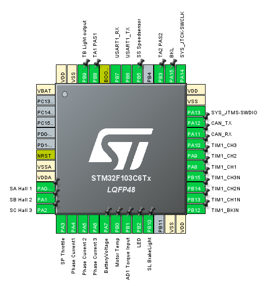
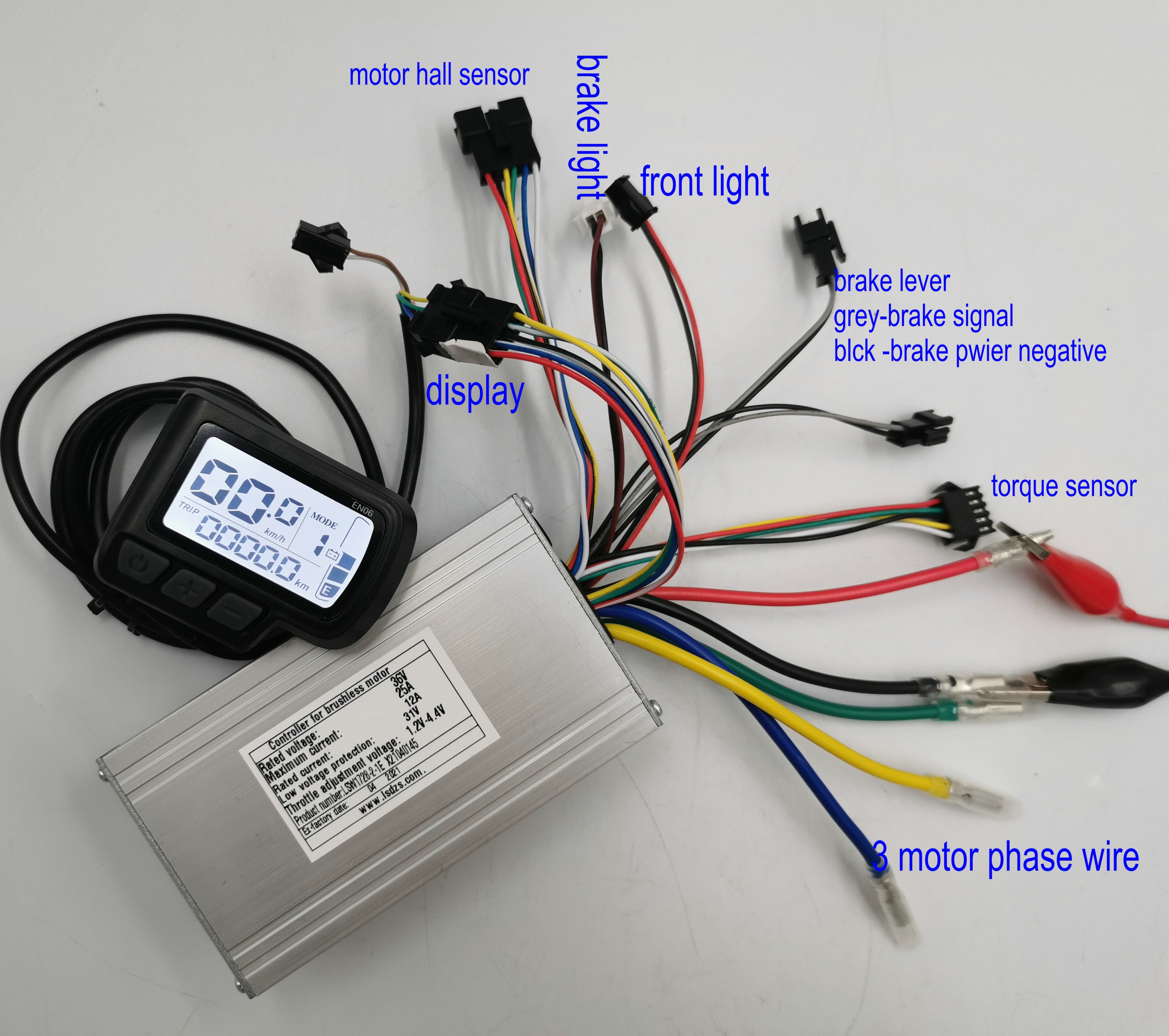
I have been through the forum, which is full of interesting information. However, I have a different problem. I don't have any external plugs for programming. I believe, from what i could make, that there is a plug going to the battery, a plug going to the rear light, one going to the motor, and one going to a mother board. The plug going to the mother board (which is another STM chip) is a 1-wire UART communication from what I could understand (two pins, RX and TX, on the STM chip are connected to the same wire that goes down to the controller).

There are not other cables. Therefore, I am quite sure the firmware on the controller is updated through this 1-wire UART and using a bootloader.

My question is: can I flash the new firmware through this 1-wire UART in your opinion?
Second question: if so, do I need a USB to 1-wire UART to flash the fw? (like this for example: 1-Wire USB Interface).

I know I could buy a new controller and LCD panel, but I would really like to use the available hardware and "hack" my first thing ever ;).

I must add, the controller is embedded in silicone, which explains why I don't want to open it and am trying to reprogram it through the existing cables.

Thank you in advance for your help!
Sabouthemad
 
Last edited:
There are not other cables. Therefore, I am quite sure the firmware on the controller is updated through this 1-wire UART and using a bootloader.
What kind of vehicle are you talking about? Some photos of the controller and the peripherals would be nice!

regards
stancecoke
 
What kind of vehicle are you talking about? Some photos of the controller and the peripherals would be nice!

regards
stancecoke
Thank you Stancecoke for your reply.

Let me introduce more information on what I have found.

The controller is for a scooter, the number is LSW 1570 41F.

This is the overall configuration.
1684609480468.png

On the oscilloscope, I checked the data signal. Every 20 ms the control board sends characters to the motor controller.
1684609674965.jpeg

The signal is a series of Bytes.
1684609704377.jpeg

Using an arduino board, I am able to read the strings of characters that are sent by the control board, with timestamps. The characters are in hexadecimal format.
1684614762729.png
When the motor controller is connected and powered up, the signal is different, as follows:
1684614835860.png

I am not sure what I can do to go forward. Can I flash the microcontroller through this wire? I am not sure I know what I am doing. Any help would be appreciated.
 
Hm, difficult to say, if the Lishui bootloader and flash tool work with single wire communication also. Just try it...

But what is your plan? The OSF will not support the dashboard protocol out of the box. You would have to find a way to send a throttle signal via UART at least.....

regards
stancecoke
 
@stancecoke hello, Im trying on a gear hub motor now, made a tiny little modification to this file, to try again if flashing fails, because im having problems with my st link. check if you like it. now on the hub im getting osciclation from 18 to 26kmh. no load rpm is 36kmh.. I tried speedshift, doesnt seem to change anything from 0 to 8, then 15 is way worse. I think it may be battery current limiting? should i try to lower iq p factor from 500 to 450? now my st link doesnt want to work at all so i thought ill just ask meanwhile. also speed on ktlcd8 gets stuck when i stop the wheel too fast.. otherwise runs good. with PLL start is a bit rough and then its silent, without it it runs well but makes a bit more noise. thanks in advance for any help
 

Attachments

  • Start_Compiling.txt
    984 bytes · Views: 5
2 hours of random numbers, found that P doesnt matter if 5 or 600... the I is the key. got best results when set at 7. thank you. any idea about the display speed getting stuck? i found that it always shows 2km-h once you touch throttle after startup, then goes to zero after first speed sensor pass... weird. also can you point me a bit to more advanced pas settings? i need to set for 12 magnet double hall pas and it has too slow response, java app settings dont help
 
can you point me a bit to more advanced pas settings?
If you want to have immediate response to moving cranks, you have to disable the direction detection. This feature needs some PAS pulses to make sure that the direction is correct. Of course you can adapt PAS timeout und ramp end to your wishes.

regards
stancecoke
 
Hm, difficult to say, if the Lishui bootloader and flash tool work with single wire communication also. Just try it...

But what is your plan? The OSF will not support the dashboard protocol out of the box. You would have to find a way to send a throttle signal via UART at least.....

regards
stancecoke
Thank you for your reply. I have two options:
- I keep the motor controller as is, without flashing it, and I decode the messages send by the current control board (on the right on the picture). Then I can flash the control board so that it sends the right messages (trottle and break) to the motor controller through UART.
- I flash the motor controller and the control board both with a firware. For the motor controller, i can use the open source one that is discussed here. And for the control board, I can write a code to send the right instructions according to the communication protocol.

What do you think ? Which seems easier for you? I prefer the first.

Do you have a sample signal that you send from the display to the motor controller with various levels of throttle and break?

Best regards,
Sabri
 
Do you have a sample signal that you send from the display to the motor controller with various levels of throttle and break?
This is the problem. The EBike Controller has several digital and analogue I/Os, where throttle, brake PAS etc. are connected directly to the motor controller. Only some settings and the assist level are sent by the display to the controller. On scooters all the "intelligence" is in the dashboard. Brake, Throttle are connected to the dashboard.
So, if you have all the peripherals on the dashboard, it would be the easiest to analyze the existing protocol and emulate it with the motor controller firmware, hoping, there is no encryption.

regards
stancecoke
I believe there is supposed to be a handshake when the dashboard is activated. But I don't know what this handshake is. But I want to solve this. Do you have an idea where I can start?

Or maybe the best is to flash the motor controller with a new firmware, for which I know the communication protocole?
 
Back
Top