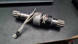
Feels like it's just red, black, gray, white, green, purple just from the wire lengths and positions:
View attachment 352380
Red and black are probably just +10V and ground anyway, so you should be able to check them from turning on your controller, plugging in the connector, and using a volt meter on the cut end attached to the connector. Once those are wired back on to the sensor, the others are likely signal wires. Many torque sensors are actually combination cadence and torque sensors. Not the end of the world to swap them around until the controller is sensing turning it correctly. Having red and black right would be enough to not destroy hall sensors, I think, unless there's a separate +5V in there for them somehow.


")