
You are using an out of date browser. It may not display this or other websites correctly.
You should upgrade or use an alternative browser.
You should upgrade or use an alternative browser.
2020/21 What's the best 100A Peak Pack?
- Thread starter BlueSeas
- Start date
BlueSeas
100 W
neptronix said:N.E.S.E with 21700's. It'll be expensive but it will be easy to build a pack.
That was impressive. I can't duplicate the vibration test. Those were not LFP? Started at 4+V, so had to be a different chemistry unless overcharged.
The N.E.S.E held up nicely, given the abuse. Which is your point I think. It would be interesting to see that test on Vruzend.
It would also be interesting to see the current draw from each cell. I'm surprised this linked article is still up since the chief engineer who wrote it has probably retired. Sold his technology to Balmar a few years ago. But while this article deals with 12V batteries, the concept of voltage drop pulling from the end of a string would have some application?
http://www.smartgauge.co.uk/batt_con.html
In my pack builds, really mostly "banks" for marine, I've been paranoid about equalizing the resistance path to each cell. Can't always be perfect, but you try. Unless I missed something, this system pulls it all from one end. So the first cell might work much harder than the last? Has anyone looked at this building ebike packs?
agniusm
1 MW
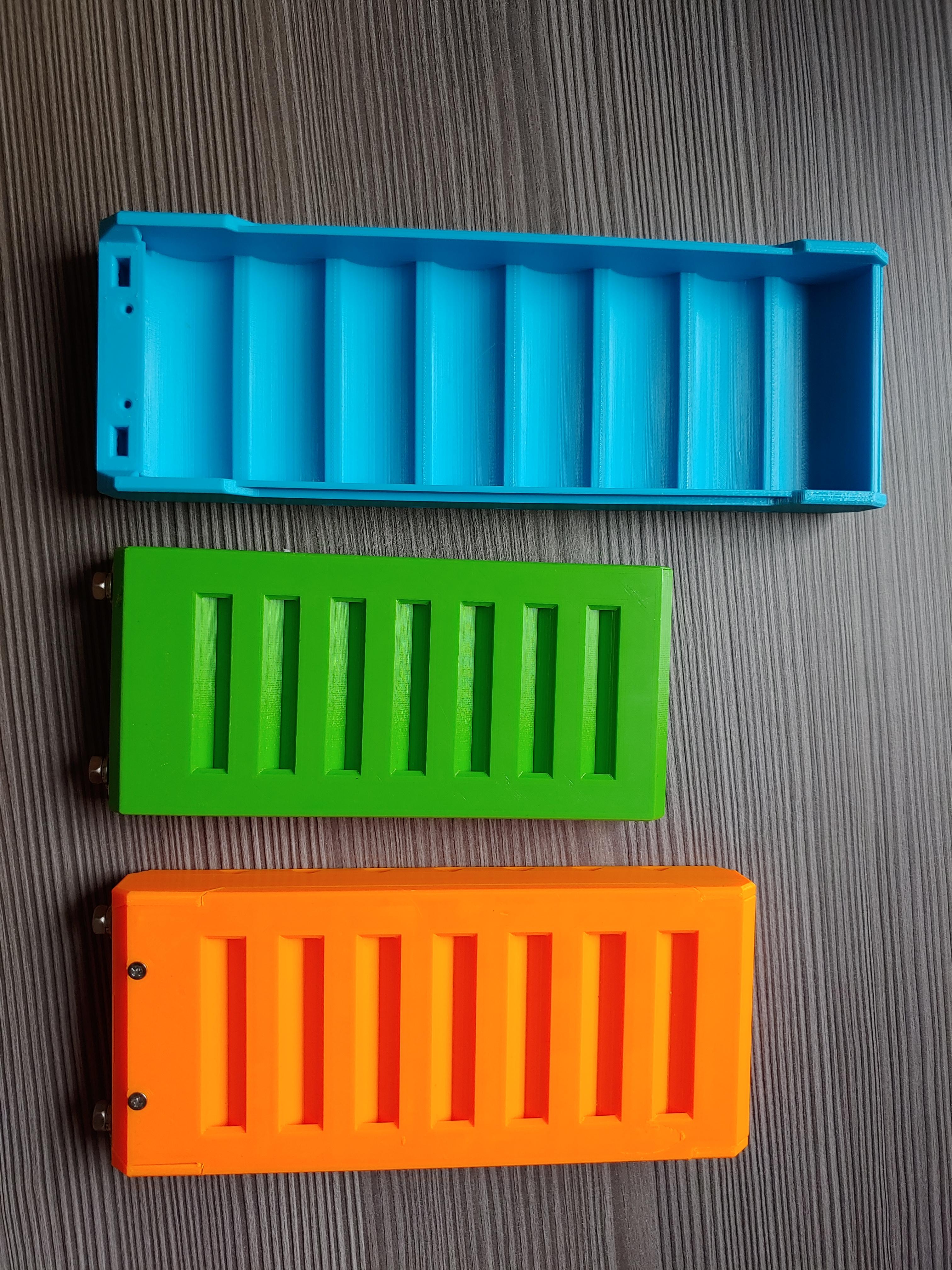
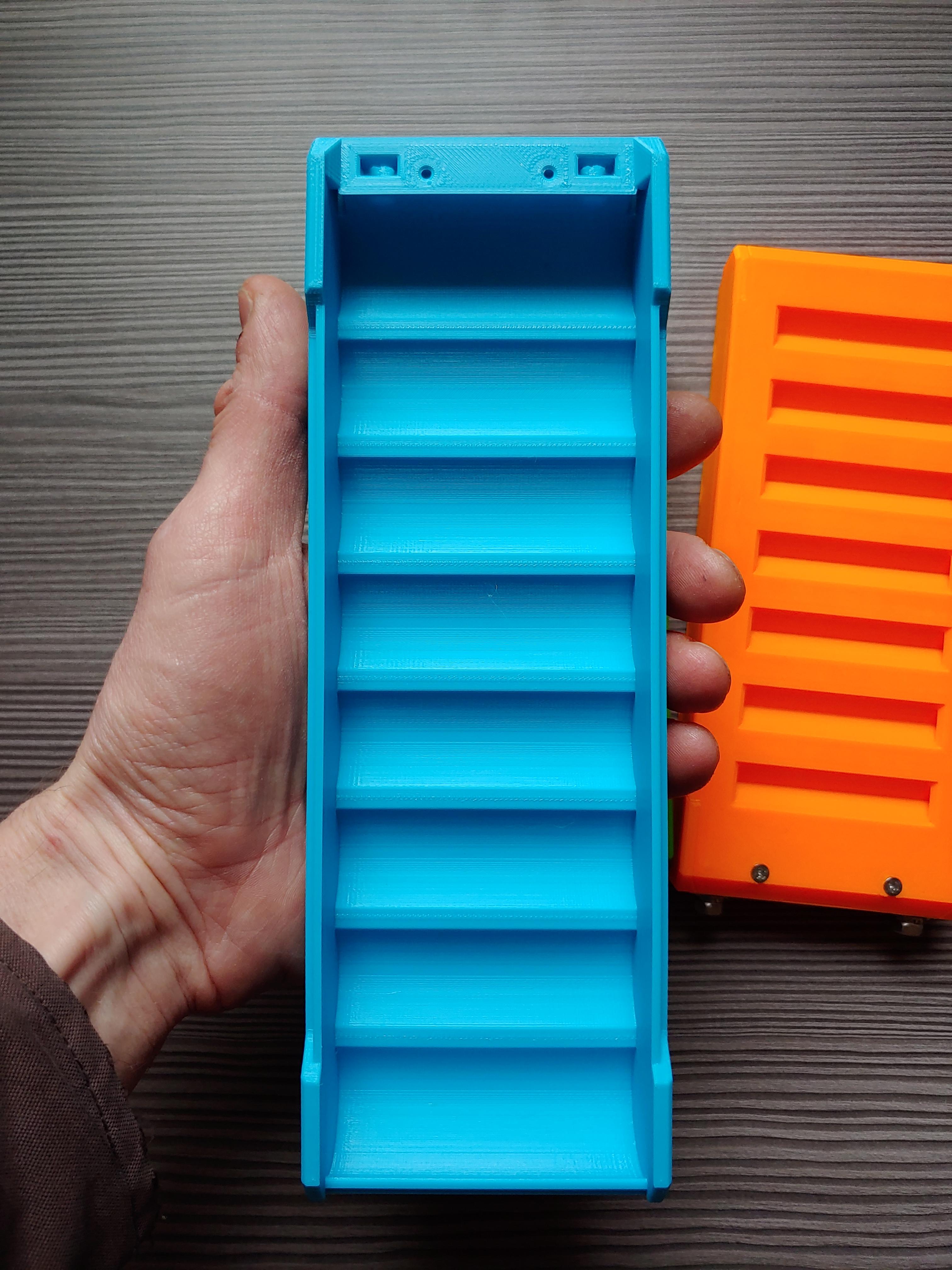
I have my modules covering most cell sizes, 18650, 21700(which can fit 20700) and 26650.
Long time ago i was making kits for A123 AMP20 prismatics but my new design for cylindrical cells is so much more convenient. My line includes modules up to 8P and i have double ended ones which are used for 2S4P or 8P, dual ended for more power throughoutput.
My modules do 70A constant and can do 200A peak easy. The benefit is that once your cells are done, you just replace them and continue using the kit. 3D files are awailable freely, should you break something, you can reprint at friends or 3d print shop. You can get in touch for more info.
Here are couole of photos:
agniusm
1 MW
BlueSeas said:http://www.smartgauge.co.uk/batt_con.html
I would skip that article. 10A draw drop in a string between couple batteries with such thick cable is nonsense.
He writes himself that it is simulated with god knows what integers.
BlueSeas
100 W
agniusm said:BlueSeas said:http://www.smartgauge.co.uk/batt_con.html
I would skip that article. 10A draw drop in a string between couple batteries with such thick cable is nonsense.
He writes himself that it is simulated with god knows what integers.
I wouldn't be so quick to dismiss his analysis. It was a different generation. Flooded lead acid. And a way different interconnect system. But this guy was one of the smartest of that generation. He made a product that accurately predicted SOC for flooded batteries by no more than a voltage reading. This is easy at rest, but his algorithm worked under load and charge.
In your implementation, the resistance for the cell closest to the serial connection bolts has a different resistance to the load than the one at the far end. The in holder bus is not evenly loaded, the part closest to the serial connection handles way more current than the opposite end. How that impacts even discharge for all cells in the holder is not known, until it's tested.
If you are interested in testing, I would suggest a max rate discharge test of a slow charged 8P holder. On completion, number the cells 1-8. Let them rest a bit. Then one by one discharge at a lower standard rate to the same minimum voltage. Compare the Ah found remaining in each of the 8 cells. There will be a measurable difference. How much? No idea.
A potential improvement would be to make the B+ and the B- from opposite sides of the holder. IF the testing shows it's worthwhile.
I applaud your system. Someone sent me the video of the 100A discharge test. It was eye opening. The system looks really good. The open source printing files are very generous. There is a real need to have packs built without welding or soldering. It's all good! But that doesn't mean there can't be improvements.
His name was Chris Gibson, aka "Gibbo" online, a very smart fella, ended up doing design consultancy for the military
and among the leading Pb bank experts globally that page is indeed canon, one of the most widely referenced on the web on DC power.
Nothing to do with LI chemistry.
Plus, talking about putting a dozen 6S packs in parallel
not something smart people do in the first place anymore, since single cells became widely available in consumer channels.
The varying load issue from connection layout is not **nearly** as great an issue when the paralleling is done at the 1S level.
If these packs were serially wired, and then put in parallel at the top level (say 20S6P rather than 6P20S) then yes, that "geographic issue" would be concerning.
If these packs were serially wired, and then put in parallel at the top level (say 20S6P rather than 6P20S) then yes, that "geographic issue" would be concerning.
agniusm
1 MW
Dont know how smart he is but he cant do 1 grade math it seems:
Having 17A difference in load between paralleled 12v batteries on 35mm2 at 100A is insane. Its easy to test.
Not saying that there is no valid point but with given scenario it is fiction.
Also, on my system i have modules that have connections on both ends, its limited to 8P but still.
Your suggestion of the testing will result in 0 difference. Parallel cells balance each other out so you will see no measureable difference.
Math would suggest that it would total at 0.00032 ohm with hes numbers."Typically the batteries are linked together with 35mm cable in a good installation (often much smaller in a poor installation). 35mm copper cable has a resistance of around 0.0006 Ohms per metre so the 20cm length between each battery will have a resistance of 0.00012 Ohms. This, admittedly, is close to nothing. But add onto this the 0.0002 Ohms for each connection interface (i.e. cable to crimp, crimp to battery post etc) and we find that the resistance between each battery post is around 0.0015 Ohms."
Having 17A difference in load between paralleled 12v batteries on 35mm2 at 100A is insane. Its easy to test.
Not saying that there is no valid point but with given scenario it is fiction.
Also, on my system i have modules that have connections on both ends, its limited to 8P but still.
Your suggestion of the testing will result in 0 difference. Parallel cells balance each other out so you will see no measureable difference.
999zip999
100 TW
You can bolt these together look at the A123 build thread on bolting together cells ez peze.
https://endless-sphere.com/forums/viewtopic.php?f=31&t=109869.
Like this.
https://endless-sphere.com/forums/download/file.php?id=82024&mode=view
I built a A123 20ah pouch battery with this method.
7years 1,485 charge cycles.
https://endless-sphere.com/forums/viewtopic.php?f=31&t=109869.
Like this.
https://endless-sphere.com/forums/download/file.php?id=82024&mode=view
I built a A123 20ah pouch battery with this method.
7years 1,485 charge cycles.
BlueSeas
100 W
john61ct said:The varying load issue from connection layout is not **nearly** as great an issue when the paralleling is done at the 1S level.
If these packs were serially wired, and then put in parallel at the top level (say 20S6P rather than 6P20S) then yes, that "geographic issue" would be concerning.
I'm not sure I understand your logic. In the linked article, they are 12V batteries, however I think about them as a new chemistry cell with 12V nominal potential. I'm pretty sure his analogy would remain the same.
What we don't have is the formula, where we would be changing the IR of the battery/cell and the operating voltage. This would modify the results.
Maybe some EE with access to a circuit simulator could validate (or not) the articles claims using his values. Then modify the circuit for 3.7V cells. It would provide at least a theoretical answer applicable to pack builds.
BlueSeas
100 W
999zip999 said:You can bolt these together look at the A123 build thread on bolting together cells ez peze.
https://endless-sphere.com/forums/viewtopic.php?f=31&t=109869.
Like this.
https://endless-sphere.com/forums/download/file.php?id=82024&mode=view
I built a A123 20ah pouch battery with this method.
7years 1,485 charge cycles.
From your picture, it looks like there is only one "pouch cell" per "level". xxS1P. There are no improvements, in reference to the article posted above possible in that configuration. That's the optimal configuration.
I'm slow to shift gears, probably your post is more oriented to my original question...the best 100A pack. That is a great picture. The materials to make that system, or one similar is something I could do. Do those rods (for clamping) go all the way through with some sort of insulation scheme? Or does each serial connection have its own clamps?
I've committed to trying the Headway 17AH cell, since I bought them already. But round 2 may very well be pouch if needed. The Kokam you linked at first blush won't fit the frame, but the A123 NMC pouch cell might.
BlueSeas
100 W
agniusm said:Your suggestion of the testing will result in 0 difference. Parallel cells balance each other out so you will see no measureable difference.
Not enough time for the cells to equalize if you break apart the paralleled group of cells right away. But there is probably a better, even easier way.
For some Headway capacity testing, I'm going to try and reopen the battery testing lab setup I used a few years ago.
But while I'm in there, I will parallel 4 cells using some wire instead of bus bars. Put them under a constant load. Take current measurements with a clamp on meter at each interconnect level. That will provide a real life answer to this question.
What gauge wire should I use? Smaller wire will make the difference larger. This would probably make it easier to see. What is the profile in mm of the bus bar you use? The limits of my testing setup is 30-40A unless I build a bank up to 12V, where I have more load options. With 4P, the max amperage of the final interconnect is 75% of the test value.
Here is a chart of voltage drop for various wire sizes at 25A. When you do a high current test, what generates the most heat? Is it the cell, the connection to the cell, or the bus bar?

Nothing would make me happier than to discover the cells are evenly loaded. Than I won't be as paranoid about equalizing the resistance path to the load for every cell in the bank.
999zip999
100 TW
Read article
Ok there is a throw rod on this through rod there is tubing like used for the refrigerator ice maker it goes on the outside the rod to insulate it it's all said in the article it even tells you what pieces to buy and what nuts the whole thread at that point is a hold your hand and walk you through it all the way to where you can buy the parts and the part numbers it's the most no braining thing you can do plus 30ah cell.
Ok there is a throw rod on this through rod there is tubing like used for the refrigerator ice maker it goes on the outside the rod to insulate it it's all said in the article it even tells you what pieces to buy and what nuts the whole thread at that point is a hold your hand and walk you through it all the way to where you can buy the parts and the part numbers it's the most no braining thing you can do plus 30ah cell.
BlueSeas
100 W
999zip999 said:Read article
Ok there is a throw rod on this through rod there is tubing like used for the refrigerator ice maker it goes on the outside the rod to insulate it it's all said in the article it even tells you what pieces to buy and what nuts the whole thread at that point is a hold your hand and walk you through it all the way to where you can buy the parts and the part numbers it's the most no braining thing you can do plus 30ah cell.
Read what article? I may have missed it, but the two links you posted didn't show details on the construction. Unless I can't read...always a possibility.
Thanks, Bob
999zip999
100 TW
Oh I gave photo have how to, hears link on the second page go look.
https://endless-sphere.com/forums/viewtopic.php?f=14&t=38761
Durtlege I think .
https://endless-sphere.com/forums/viewtopic.php?f=14&t=38761
Durtlege I think .
Clearly you don't, and what "analogy"?BlueSeas said:I'm not sure I understand your logic. In the linked article, they are 12V batteries, however I think about them as a new chemistry cell with 12V nominal potential. I'm pretty sure his analogy would remain the same.
The issue there is uneven current rates when paralleling too many serial strings, thus uneven wear, thus reduced reliability and lifespan of the bank overall.
Really the solution is no more than two strings, ideally just one. Smart people just don't use a bunch of 12V units to build deep cycling banks anymore anyway.
But they act nothing like 12V cells in any case.
Cells in parallel (IOW @1S) function as a single battery, no uneven current rates, that page is just irrelevant to that scenario.
BlueSeas
100 W
999zip999 said:Oh I gave photo have how hears link on second page go look.
https://endless-sphere.com/forums/viewtopic.php?f=14&t=38761
Durtlege I think .
That is the link! Just skimmed so far, but clear it holds answers. Thanks!
BlueSeas
100 W
john61ct said:Clearly you don't, and what "analogy"?BlueSeas said:I'm not sure I understand your logic. In the linked article, they are 12V batteries, however I think about them as a new chemistry cell with 12V nominal potential. I'm pretty sure his analogy would remain the same.
The issue there is uneven current rates when paralleling too many serial strings, thus uneven wear, thus reduced reliability and lifespan of the bank overall.
Really the solution is no more than two strings, ideally just one. Smart people just don't use a bunch of 12V units to build deep cycling banks anymore anyway.
But they act nothing like 12V cells in any case.
Cells in parallel (IOW @1S) function as a single battery, no uneven current rates, that page is just irrelevant to that scenario.
A 12V FLA battery is 6 cells in serial. Granted. But in the context of this discussion it's a 12V cell. The issue of paralleled doesn't go away. Cells...or Banks in series DO pass equal current in a circuit. But that doesn't mean all cells contribute equally.
999zip999
100 TW
A set of kokram cells 16s and how many amps for how many watts. Math... Cheap EZ those cells will be gone tomorrow. But you asked us before you buy.
agniusm
1 MW
BlueSeas said:agniusm said:Your suggestion of the testing will result in 0 difference. Parallel cells balance each other out so you will see no measureable difference.
Not enough time for the cells to equalize if you break apart the paralleled group of cells right away. But there is probably a better, even easier way.
For some Headway capacity testing, I'm going to try and reopen the battery testing lab setup I used a few years ago.
But while I'm in there, I will parallel 4 cells using some wire instead of bus bars. Put them under a constant load. Take current measurements with a clamp on meter at each interconnect level. That will provide a real life answer to this question.
What gauge wire should I use? Smaller wire will make the difference larger. This would probably make it easier to see. What is the profile in mm of the bus bar you use? The limits of my testing setup is 30-40A unless I build a bank up to 12V, where I have more load options. With 4P, the max amperage of the final interconnect is 75% of the test value.
Here is a chart of voltage drop for various wire sizes at 25A. When you do a high current test, what generates the most heat? Is it the cell, the connection to the cell, or the bus bar?
Nothing would make me happier than to discover the cells are evenly loaded. Than I won't be as paranoid about equalizing the resistance path to the load for every cell in the bank.
I think you are overthinking and overcomplicating things. Sometimes OCD is a bitch
")
In case of my modules, 21700 8P voltage drop between first cell and last cell in the module is 0.021V @ 50A. You add cell balancing in parallel groups and its nothing. There is plenty of time for cells to equalize. That's why when building parallel groups you need cells to sit as same or very close to same SOC so there was no extreme inrush currents flowing to lesser cells.
BTW getting back to your 12V article, 35mm^2 cable voltage drop at 100A 1000mm is 0.065V. Its nothing.
BlueSeas
100 W
Voltage drop is bigger than you think. And yep...I have those tendencies! I will give you a couple examples.
Make 2 packs/banks of 24V at 1000Ah using 80 100Ah LFP cells. These 2 banks normally operated in parallel for 2000Ah at 24V. That's something near 50 KWH. The parallel connection is double 4/0 cables. Decouple the banks. Fully discharge (almost) one to 3V per cell, fully charge the other to 3.5V. Based on testing, this would be about 10% and 97% SOC respectively. Bank voltage 24V and 28V respectively. Now reconnect them in parallel. What happens? Nothing. Well not exactly, but no smoke, heat or any cells exceed limitations. Why? The banks are about 25 feet apart and even with doubled up 4/0 cable there is voltage drop. The moment the connection is made, there was an initial 500A surge, by the end of the first minute the rate was down to about 125A. I don't remember by exactly how much, but even overnight the banks never equalized charge. The only way to perfectly re sync the banks was to decouple and take each to full charge then reconnect. Otherwise the BMS of the high side stopped the charge before the low side caught up.
At the time, we couldn't find anyone who had tried this before. Some predicted a fire and smoke, I had run enough calculations to believe it safe, but was ready to break the connection at 1000A if necessary. You might ask why, well there was a procedure manual to write for the vessel captain, it had to have operational limitations. The system was designed to operate if needed on one bank, while one bank had maintenance or other operational issues.
The second example much simpler, I'm pretty sure other's do this too. But an easy load to use during bank building is 50 - 60ft of AWG 18 wire. Calibrate the exact length to about 15A when shorting a fully charged cell. Use at least 105 degree C wire and don't coil it up. You can use that without limitation. Want 30A? Make two. I've used this with timer switches to take carts of cells all in parallel from full charge to a nearly calibrated 50% SOC for storage. Want to sync a 12V bank of cells? Set the charger for 15A and pop one of these puppies on each cell when it reaches full charge and wait for the rest to catch up.
The point is voltage drop is a consideration. Not completely sure how significant. But will know more soon.
BlueSeas
100 W
999zip999 said:A set of kokram cells 16s and how many amps for how many watts. Math... Cheap EZ those cells will be gone tomorrow. But you asked us before you buy.
When I started the thread, I hadn't purchased anything. I have now...gonna try some Headway's. If that doesn't pan out, I will probably go to the pouch cells. At first blush, those kokram cells are too big for the space available, especially if I want to be able to take them on and off as a single unit. Plus I want 72V minimum, and that calls for 20 cells.
I have my eye on these:
https://a123batteries.com/a123-systems-3-7-volt-26ah-prismatic-pouch-cell-amp26-nmc/
A little smaller with less capacity than kokram. But think they will fit. Cheaper than the Headway's...but that's for just the cells. Haven't seen much discussion on these, but I haven't spent much time looking yet. They are a really good value on the $$ per amp scale.
999zip999
100 TW
I like A123 quality haven't tried or heard much about NMC but looks good if fits as a big problem with pouch cells. Going the read your link.
That's some crazy risky experimenting there!
I actually want to "productize" a generic current limiter for exactly that use case
plugging large depleted sub-packs back into the Full "mother bank" in parallel.
Yes excellent cells!
Just realize not LFP, more like an "EV LiPo" higher density but much greater thermal risk
I actually want to "productize" a generic current limiter for exactly that use case
plugging large depleted sub-packs back into the Full "mother bank" in parallel.
BlueSeas said:I have my eye on these:
https://a123batteries.com/a123-systems-3-7-volt-26ah-prismatic-pouch-cell-amp26-nmc/
A little smaller with less capacity than kokram. But think they will fit. Cheaper than the Headway's...but that's for just the cells. Haven't seen much discussion on these, but I haven't spent much time looking yet. They are a really good value on the $$ per amp scale.
Yes excellent cells!
Just realize not LFP, more like an "EV LiPo" higher density but much greater thermal risk
Similar threads
- Replies
- 4
- Views
- 527
- Replies
- 34
- Views
- 3,476
- Replies
- 47
- Views
- 3,574
- Replies
- 18
- Views
- 2,785
- Replies
- 31
- Views
- 3,183