20Kw motor and 300A ESC (ultralight aircraft propulsion system)

I have made a die (jaws) for crimping cable lugs, for 35 and 25 sqmm cables, i followed the specifications for hex size for correct crimping. I came out nice, a big vice (100mm at least) is needed to make a good crimp. Here a few photos of the die and a crimped cable and lug.
IMG_20211203_130907.jpg
IMG_20211203_130957.jpg
IMG_20211203_131135.jpg
 
Mihai_F said:
mxlemming said:
Did you split the blue ground plane?

There are 3 physical separate boards, so yes the blue gnd plane is split

I meant on each individual board. Is it continuous on the whole board or did you make it house shoe shaped?
 
mxlemming said:
I meant on each individual board. Is it continuous on the whole board or did you make it house shoe shaped?
Yes is continous under and connected only to B-
Edit: and the inner lower (purple) the unused part in the middle is also grounded (B-)
 
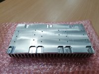
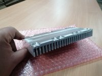
A bit of progress, i drilled the heat sink (200x100x25mm) and machined the slots to give clearance to the boltheads of the cable lugs, it came out nice. The sink is extruded Al, and on 200mm length was out of plane about 1mm in the center, so i had to do some fine pressing to bend it back in to plane.

IMG_20211207_080645.jpg
IMG_20211207_080558.jpg
 
Super jealous of your CNC stuff. Always so nice compared to the stuff i 3d print and drill with my Makita.

I need to buy myself a mini mill.
 
mxlemming said:
Super jealous of your CNC stuff. Always so nice compared to the stuff i 3d print and drill with my Makita.

I need to buy myself a mini mill.

Yeah... i feel you, that is that way that i felt when i saw 4 layer pcb-s around here, then i tried JCL-PCB, i was reluctant to try it, i taught is is expensive and complicated, but now i can have 4 layer pcb-s too.
You can try to give your parts to a machine shop they might charge about 50 to 100 euro per hour of machining, and materials: Al 6061T6 round bar is about 7 euro/kg , steel C45 is about 3 euro/kg , Cr42Mo is a bit more, so it is doable.

Don't be fooled about mini mill CNC, they'r rigidity is poor, rigidity in a CNC is like "inverse of" inductance in a high power PCB, the higher the rigidity and the lower the inductance the better, inductance causes ringing, low rigidity cause vibration of the milling head and the finished product looks poor (vibrated surface), and many broken tools, vibration kills carbide tools.
Even the CNC mill in the shop that i work has limitations because of rigidity, and you would think a 5 ton machine made out of cast iron is rigid as heck, but is not.
About 10 years ago i built with a friend a CNC mill, we did not know much about what makes a good CNC, then we learned the hard way...rigidity is the no.1 cause of the problems.
So a flimsy china made CNC can do small parts at a ok level of quality, but when you need to mill with a 10mm diameter 50mm long milling tool (deep milling), then there is a problem. And we are talking about milling ALUMINUM, in steel is way worst, you just can't mill steel and have quality surface with an aluminum frame CNC.
I have seen some people take an old milling machine and transform it in to a CNC, that will give better results if the machine is not worn out of shape and does not have tons of play and backlash.....
So your best bet is go to a decent CNC shop, that way you will get good parts with good tolerances and nice surface finish.
 
CNC shops around the UK want large amounts of money for my parts. It's not really hobby affordable.

I'm certainly not going to buy a junk "CNC". Wondering if i can get an old Bridgeport out something like that.
 
mxlemming said:
CNC shops around the UK want large amounts of money for my parts. It's not really hobby affordable.

I'm certainly not going to buy a junk "CNC". Wondering if i can get an old Bridgeport out something like that.

Have you tried to get a quote from pcbway ? For instance shops in Europe asked me 180e for a part, PCBway did the job for 90e. There are many option available in terms of material or finishing, tolerances and so on.
 
atkforever said:
mxlemming said:
CNC shops around the UK want large amounts of money for my parts. It's not really hobby affordable.

I'm certainly not going to buy a junk "CNC". Wondering if i can get an old Bridgeport out something like that.

Have you tried to get a quote from pcbway ? For instance shops in Europe asked me 180e for a part, PCBway did the job for 90e. There are many option available in terms of material or finishing, tolerances and so on.

https://www.pcbway.com/rapid-prototyping/cnc-machining/
 
mxlemming said:
atkforever said:
mxlemming said:
CNC shops around the UK want large amounts of money for my parts. It's not really hobby affordable.

I'm certainly not going to buy a junk "CNC". Wondering if i can get an old Bridgeport out something like that.

Have you tried to get a quote from pcbway ? For instance shops in Europe asked me 180e for a part, PCBway did the job for 90e. There are many option available in terms of material or finishing, tolerances and so on.

https://www.pcbway.com/rapid-prototyping/cnc-machining/

Yes?
 
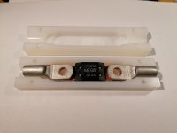
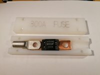
A bit of progress here, i have made a fuse box to encase the fuse witch will be bolted to the battery + cable, now i know that fuse is rated at 32V and i'm pushing 92V thru it, it might arc a bit when it blows, but still better then nothing and blowing up my power board, i'm aiming for a bit less damage if the fet-s get shorted.
The boards arrived, i'm impressed with they'r quality and tolerances, far better than local my pcb supplier.
I'm still waiting for the metal parts, case and busbars, that are cut and bent at the metal work shop, they only do guillotine cutting and bending, then i will have to machine the holes in to them.
Here are a few pictures.
IMG_20211218_053012.jpg
IMG_20211218_053033.jpg
IMG_20211218_053216.jpg
 
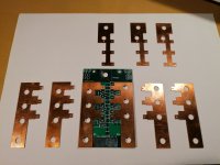
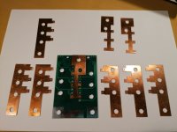
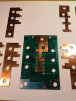
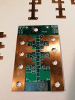
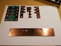
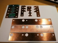
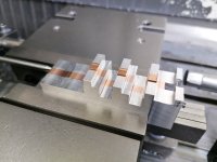
A bit of progress, i had some time to machine the bus-bars and the case, the pcb bus bars ware a bit of headache to make since they are so small and thin, the copper is so soft i had to add some aluminum plates to support the copper in order to be able to machine it (see photo). Now i have all the parts and soon i'l start assembly.
I wish you a happy "conductive" :bolt: new YEAR, and may all the smoke remain inside your FET-s :p

IMG_20211231_113100.jpg
IMG_20211231_113242.jpg
IMG_20211231_113259.jpg
IMG_20211231_113337.jpg
IMG_20211231_113447.jpg
IMG_20211231_113515.jpg
IMG_20211231_113720.jpg
IMG_20211229_203030.jpg
 
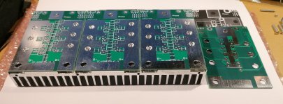
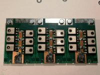
I put together the power boards, i came out nice and sleek, now i have to solder the FET-s and DC-link caps , make the big cables, and a few things here and there, then some testing.
IMG_20220107_120215.jpg
IMG_20220107_120309.jpg
 
This is beautiful. Hope it works! If it does, it should take all the power!

Big laminated DC bus a very good call. Might just solve all the inductance issues in one hit.
 
Great job in your power bus packaging. You've got way above average electrical and thermal conductivity, and tight inductance. I'm excited to see how they perform, I may need to make or buy some for my own projects.
 
I just noticed you populated the snubbers and a load of gate to source capacitors already. How did you know what values to use without testing and what did you choose?

They should be in the 1-10nF region (similar to the output capacitance of the FETs but not actually the same) and the snubber resistors 0.5 to 2 ohms.

It's slightly complicated by your having 6 of them, half each to V+and ground (you only need one of these since for high frequency with such a lovely low inductance V+and ground are basically the same) so calculated values would be C/6 and Rx6.

I have a question about your fuse. It's 32V and you're running 96V you say. Have you ever blown one at these voltages? I'm also using them for home projects at 20s lithium and haven't ever blown one. Just looking at them it seems impossible to me that they wouldn't blow and withstand 96V but the higher voltage ones are ridiculously big and I wonder why.

Infuriating that semiconductors we always have to divide ratings by 2 in best case use but fuses we can multiply by 3.
 
mxlemming said:
I just noticed you populated the snubbers and a load of gate to source capacitors already. How did you know what values to use without testing and what did you choose?

I have a question about your fuse. It's 32V and you're running 96V you say. Have you ever blown one at these voltages? I'm also using them for home projects at 20s lithium and haven't ever blown one. Just looking at them it seems impossible to me that they wouldn't blow and withstand 96V but the higher voltage ones are ridiculously big and I wonder why.

When i did the last testing of the V1.3, i tested with 10nF GS (on low side) caps and 22ohm gate R, and this gave a nice and stable (ringging free) gate waveform, so now on V1.4 i'll go first with same GS cap but a bit lower R gate (12ohm) to switch a bit faster and have a stronger drive on the gates, now this is for first testing and i might change it... it might not need the GS caps at all, will see. I think that staring wit similar values of something that gave good results is a good starting point.
The snubbers i selected 4,7nF with 1.1ohm for start, and i have put them on each low side fet-s only for now. On each fet mainly because i have seen it worked great on peters controller. And on low side fet-s, because only low side fets do the PWM, and on the previous versions when testing the high side snubbers din nothing different, the high side fet-s behaved ok on all versions, the low side fet-s had the spikes and the ringing and all the nastiness, so this setup is for start now, then i'l see how it does, i might remove the snubbers if they do not much improvement.

I did not test those fuses, first time use for me, but i read a few things about fuses. The main reason the fuse dimension grows with the increase in voltage rating, is because of the arcing potential, the bigger the voltage the bigger the gap has to be after the fuse strip vaporizes so that no arcing can occur. In other words an 12V 100A auto fuse will brake at same 100 ish amps at 12V as at 400V, but at 400V it will continue to arc until it melts itself and stuff around it... its like when they open a 30000V line switch at the transformation station, on the first centimeters of the opening it arcs. Auto fuses a more precise than mains 220/400v fuses....
So yes a 32V fuse when blowing up at 96V might (or not) arc a bit (a second) until i pull the emergency disconnect handle. But way better than vaporizing the fet-s and bus bars, so my experiences with that mayhem, vaporized fet-s, has to stop, that level of obliteration only the first time was impressive to see :D
 
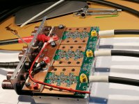
A bit of progress, the power module is almost ready to be connected to the command module, most of the things are done.
Because it was designed from ground up on computer, and then CNC executed, the fitment of every thing went smoothly and flawless, the assembly of everything was a LOT more easy and practical, then previous versions, mostly because of the bolted heavy cables, soldering 35sqmm cables is a real P.I.T.A. . Now i'm not sure is the nut isolators will stay or leave, but they look neat.
The current sensor is on the positive batt cable (the red ring with wires coming out of it), temp sensor is also installed, and the wires for power to the command module. I also corrected the GND (Vs) conections of the gate drives on the command module to be directly to the fet-s. The fet-s legs i left them long so i can connect the scope probes to them when i do the testing, under the board there is no chance to attach them. Soldering of the heavy stuff on bus bars was done with a 100W soldering iron cranked down (30%) a bit the temp, and it was nice and easy, the other versions i had to use the 400W heavy iron, witch is a beast to handle plus the radiated heat is immense... :D
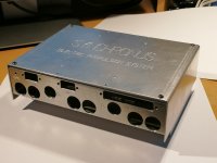
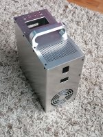
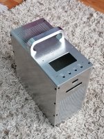
I had an nice "oportunity" to machine the case of the battery charger (that is a separate project).
So here are a few photos.
IMG_20220118_155330.jpg
IMG_20220112_230140.jpg
IMG_20220114_125501.jpg
IMG_20220114_125517.jpg
 
Looks great my friend.

I use a cold forging type hydraulic cable crimper that will do up to 750MCM sized lugs. I would be honored to crimp whatever wire and terminals you would like to use, and mail them to you (for free). Let me know your favorite cable gauge and lug size ID and lengths. I have tons of 0000awg, 0awg, 2awg, 4awg cable and big ring terminals handy here at the RnD lab.
 
liveforphysics said:
Looks great my friend.

I use a cold forging type hydraulic cable crimper that will do up to 750MCM sized lugs. I would be honored to crimp whatever wire and terminals you would like to use, and mail them to you (for free). Let me know your favorite cable gauge and lug size ID and lengths. I have tons of 0000awg, 0awg, 2awg, 4awg cable and big ring terminals handy here at the RnD lab.
Hy, thank you for your appreciation and your offer, I'll keep it in mind for some future projects 😉.
 
It's so beautiful. Not much more to say. Hope it works as well as it looks.

A slightly out there idea... Could you connect from the ceramic cap nearest the laminated busbar to the busbar with a really short twisted pair?

The only remaining avoidable inductance is between your busbar and the power boards since the screws are quite separated. If you connect them with a low inductance link, your inductance is almost entirely the MOSFET legs which you can't really do anything about.

What about your gate driver situation? I presume you're powering the gate board from the flying leads coming off the power busbar. These don't form a 10cm ground loop with the gate driver returns do they?
 
mxlemming said:
...
A slightly out there idea... Could you connect from the ceramic cap nearest the laminated busbar to the busbar with a really short twisted pair?
...
What about your gate driver situation? I presume you're powering the gate board from the flying leads coming off the power busbar. These don't form a 10cm ground loop with the gate driver returns do they?
I might try to solder a twisted pair between pcb-s and busbars, will see.
Nope, no ground loop, i modified the traces, so that gate drivers do not have the Gnd (Vs) connection to the fet-s thru the same Gnd as the command board, now they have each separate Gnd (Vs) connection to each phase board, and the wires (gate and Vs) wil be in twisted pairs.
 
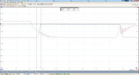
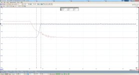
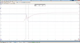
I did some testing, all tests ware with motor and no load (prop).

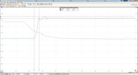
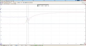
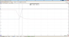
First tests ware at 30v at 1A with Rg 12ohm Cgs 100n and low side snubb R1,1 C4,7n, and the results ware not quite ok, there was some wired oscillation at the end of Ls fet Vds rise time, i made some test at 90V and the ochillations ware way worst (forgot to save the waveforms), so i blamed Cgs, and removed them.
Here is the probing, the Vds had low inductance probing, Vgs din not unfortunatly and as you will see it might had introduced artifacts...
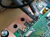
IMG_20220127_131658.jpg
Low side fet rise time
V1_4 30V LS fet rg12+cg+snub rise 1 .jpg
High side fet fall time
V1_4 30V HS fet rg12+cg+snub fall 1 .jpg
High side fet rise time
V1_4 30V HS fet rg12+cg+snub rise 1 .jpg
The High side fet-s seem ok.

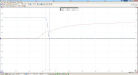
Test 2 at 30v at 1A with Rg 12ohm Cgs, and snubbers Rmoved, the results ware better, there is some oscillation at Ls fet Vds rise time, but nothing to bad.
Low side fet rise time
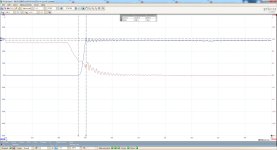
V1_4 30V LS fet rg12 rise 1 .jpg
Low side fet fall time
V1_4 30V LS fet rg12 fall 1 .jpg

Test 3 at 40v at 2A with Rg 12ohm Cgs, and snubbers Rmoved, the results ware even better as Cds drops with increase in voltage, the oscillation amplitude did not increase at Ls fet Vds rise time.
Now the gate presents some oscillations but i believe it is measuring artifacts, because of probing.
Low side fet rise and fall time
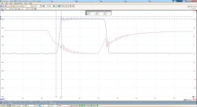
V1_4 40V LS fet rg12 rise + fall 1 .jpg

Test 4 at 65v at 3A with Rg 12ohm Cgs, and snubbers Rmoved, the results ware still better as Cds drops with increase in voltage, the oscillation amplitude did not increase at Ls fet Vds rise time.
Low side fet rise time
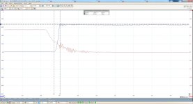
V1_4 65V LS fet rg12 rise 1 .jpg

Test 5 at 90v at 8A almots full throttle (~98% ish dutycycle) with Rg 12ohm Cgs, and snubbers Rmoved, the results ware still better as Cds drops with increase in voltage, the oscillation amplitude did not increase at Ls fet Vds rise time.
The gate presents the same funky oscillations at turn on, i think miller because Vgs shuts up as Vds starts to go down and then Vgs goes down as Vds goes down, and this phenomenon is more pronounced as i increases the input voltage throughout the tests, but i might be measuring artifacts, because of probing, and mostly there is nothing on Vds fall time to reflect what happens on gate....at least that is what i think...
Low side fet rise and fall time
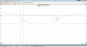
V1_4 90V LS fet rg12 rise + fall 1 .jpg
V1_4 90V LS fet rg12 rise + fall 2 .jpg
Low side fet rise time
V1_4 90V LS fet rg12 rise 1 .jpg
Low side fet fall time
V1_4 90V LS fet rg12 fall 1 .jpg
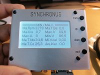
Here is the log from controller showing the max voltage and current on test 5
IMG_20220127_132537.jpg

All in all it performed well it spun the motor to 3200rpm, stayed cool, all waveforms ware consistent there ware no wired pulses and spikes like on V1.3 tests, so so far so good.
Next month i'l get a new scope (100Mhz BW), with my picoscope, i'm way over its BW and samplerate limits now, i'l redo the 90V no load tests with the new scope, and report back, until then please comment on what you think i presented here.
 
Not looking bad, but let's see how it does under load.

The thing I learnt the hard way with snubbers was that you actually have to tune them, not just use random larger values. Bigger isn't always better.

For my first PCB I guessed their value and they made it worse, and i ended up removing them since it was fine without.

You may have read I recently had a play with another user here's board and did take the time to calculate the snubber values... The result was an enormous improvement.

100MHz siglent 4 channel scope is one of the best investments I've ever made. I love it.
 
mxlemming said:
Not looking bad, but let's see how it does under load.

The thing I learnt the hard way with snubbers was that you actually have to tune them, not just use random larger values. Bigger isn't always better.

For my first PCB I guessed their value and they made it worse, and i ended up removing them since it was fine without.

You may have read I recently had a play with another user here's board and did take the time to calculate the snubber values... The result was an enormous improvement.

100MHz siglent 4 channel scope is one of the best investments I've ever made. I love it.

The snubber components ware calculated to some degree, for damping 0,75 at a freq of 22mhz, but was calculated on estimated inductance, and the real ringing freq i can not measure at this moment, anything over 20mhz is eronous, 100Ms/s limit on my picoscope. So i wait for the new scope to get the real ringing freq and redo the snubber calculations then.

For load test i'm investigating to do a double pulse test first, testing with motor and prop outside might have to wait a bit because is full winter here, snowing and -10degC...

If anyone has some hints how to do a double pulse test, i now how to code it and how to implement it, but i don't know how to determine the pulse lengths and spacing... The current i can measure it with the scope directly of the current sensor, and do the math to get the current.
 
Back
Top