20Kw motor and 300A ESC (ultralight aircraft propulsion system)

I wrote a double pulse test routine by just writing 100% duty and every pwm period reading the current on the low side shunt and when it went over my amp request turn it off for one period then back on for one period at low (10%) duty... Then turn all off.

There's no magic to it.

Use V= Ldi/dt to estimate the number of pwm periods.

Run it at low voltage with a current limited PSU to start.

Then batteries with a tiny fuse (like 1/10 the intended pulse size, it shouldn't blow with a<<1ms pulse.

I used a motor as the inductive load because it was already attached. Peters used a coil of thick wire.
 
Mihai_F said:
If anyone has some hints how to do a double pulse test, i now how to code it and how to implement it, but i don't know how to determine the pulse lengths and spacing... The current i can measure it with the scope directly of the current sensor, and do the math to get the current.

Turn on the device under test until the desired test current is reached.
Turn off the device under test and allow any oscillation to settle, 10-50us is usually plenty
Turn on the device under test for a predetermined amount of time, then back off. This second pulse demonstrates how the device behaves when it turns on into the given current.

The purpose of the double pulse test is to create a repeatable set of conditions so you can observe how changes affect the design, snappiness of reverse recovery, current tail (IGBT), gate resistors, snubber effect, etc. Super useful way to test.
 
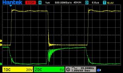
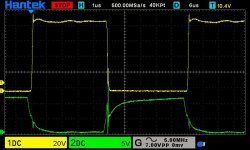
I did the double pulse test with the new scope, the tests are done using the motor as an inductor (10uH 6mohm), and one phase low side switching and another phase high side turned on. I started at 24V with first pulse from 10 to 100 us then a 5us pause then second pulse 5us, witch gave pulse currents from 23A to 230A, then increased voltage to 40V same timing with first pulse from 60 to 100us, witch gave pulse currents from 230A to 380A, then increased voltage to 65V same timing with first pulse 60us, witch gave pulse current 380A, then increased voltage to 90V same timing with first pulse 50us, witch gave pulse current 440A.
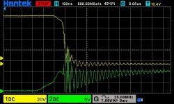
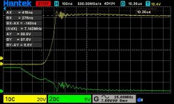
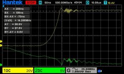
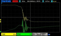
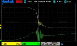
I attached only the 90V test shots of Low side fet (only low side switching), the overshoot is 8,8V at 440A, there is a bit of ringing but nothing bad, the gate ringing is probing (the 3" long alligator clip) artifact to some degree, i'l have to measure the gate alone using low inductance probing.
I am impressed with the results, all the redesign and your advice followed paid off.
In the next day i'l do more testing, i think i'l go up to pulse 550A if all is ok, but i'l have to redo the gate shots first.
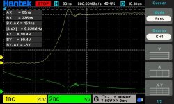
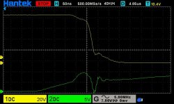
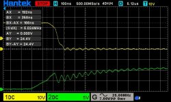
green Vg , yellow Vds
Ls fet second pulse
dso_01_01_01_47_56.jpg
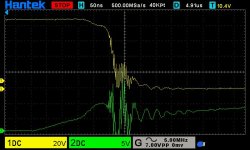
Ls fet fall time
dso_01_01_01_49_05.jpg
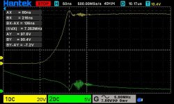
Ls fet rise time
dso_01_01_01_53_28.jpg
Ls fet rise time zoomed
dso_01_01_01_54_18.jpg
 
Mihai_F said:
I am impressed with the results, all the redesign and your advice followed paid off.

For the part I've played, you're very welcome. It's fantastic to see this go from it's old state to one of the most physically beautiful and now it seems remarkably well switching things.

You should retry with ground springs(didn't they come with your scope?) or soldered in twisted pairs everywhere, the ground clips are very ringy. In fact I'm quite surprised you've gotten results as good as you have there.

Few other questions:
Which MOSFETs was this tested with? (The ringing in the gate looks somewhat like you're using the ones with high reverse transfer capacitance but perhaps it's just noise from the ground clips/common mode/it's just a nasty environment for the scope).
How did you measure this current?

Few other ideas:
Might be able to remove the last of the ringing on the fall by tuning the snubbers. As I said before, wrong snubbers can actually make things worse than no snubbers.

But overall, this looks just fine. More than fine, for 440A switching with artifacts all but gone within a few hundred ns this seems really good.

Let's hope your driver/bldc control stage plays nicely with it at high power now!
 
mxlemming said:
For the part I've played, you're very welcome. It's fantastic to see this go from it's old state to one of the most physically beautiful and now it seems remarkably well switching things.

yep, thak you for your time and help!

mxlemming said:
You should retry with ground springs(didn't they come with your scope?) or soldered in twisted pairs everywhere, the ground clips are very ringy. In fact I'm quite surprised you've gotten results as good as you have there.

Few other questions:
Which MOSFETs was this tested with? (The ringing in the gate looks somewhat like you're using the ones with high reverse transfer capacitance but perhaps it's just noise from the ground clips/common mode/it's just a nasty environment for the scope).
How did you measure this current?

It din came with ground spring, only the Vds was probed with ground spring
Fets are IRF150P220, it might a bit of reverse transfer there, test was done without snubbers and without Cgs caps.

Current was monitored with my picoscope on the current sensor, and as a cross check i calculated the current based on pulse length, voltage, inductance, inductor resistence and Rds_on, and the numbers are about the same, so the current measurement is good.

mxlemming said:
Few other ideas:
Might be able to remove the last of the ringing on the fall by tuning the snubbers. As I said before, wrong snubbers can actually make things worse than no snubbers.
I redid the 90V 440A test with ground spring also on the Vgs, it inproved a bit, i might try only the Vgs on a diffrent probing way tomorow. I might add some small Cgs cap in series with a resistor (like peters did), calculated to form a low pass filter/snubber for the 30Mhz ringing on the gates.
Phase snubbers,.... i might try.
 
Looking at this again, the thing I'm finding most troubling is that the oscillations on gate and phase are identical in phase and magnitude. Exactly the same voltage.

They shouldn't be. Miller transfer leading to instability (which i don't think those fets will have) should see a hugely bigger oscillation on phase than gate, with a phase shift, and parasitic inductance/capacitance oscillation should be much less visible on gate.

I wonder if this is some ground loop or common mode interference with your scope... Did you use a power supply or battery for this test? Perhaps there's a big old ground loop between supply and scope and wall.

Or maybe the hantek scope is just out of its league here, this is a fairly harsh measurement environment. Or other.
 
mxlemming said:
Looking at this again, the thing I'm finding most troubling is that the oscillations on gate and phase are identical in phase and magnitude. Exactly the same voltage.

They shouldn't be. Miller transfer leading to instability (which i don't think those fets will have) should see a hugely bigger oscillation on phase than gate, with a phase shift, and parasitic inductance/capacitance oscillation should be much less visible on gate.

I wonder if this is some ground loop or common mode interference with your scope... Did you use a power supply or battery for this test? Perhaps there's a big old ground loop between supply and scope and wall.

Or maybe the hantek scope is just out of its league here, this is a fairly harsh measurement environment. Or other.

I scoped only the gate with the short ground spring directly on fet legs (like photo from few posts early), DUT is battery powered, there is no ground loop, only one probe was connected to DUT.
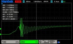
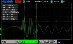
My main concern is that p-p Vgs on that ringing is 20,6V, that is no good, and some crazy 178Mhz bursts ringing(see the zoomed one)
I will calculated some snubbers, put them on and scope again.
dso_01_01_00_21_16.jpg
zoomed
dso_01_01_00_35_14.jpg
 
I calculated a phase snubber (one, an C and an R) for 30Mhz, 0.25 damping (to keep R at 0.6W disipation), 4,7nF 1,1R, it did make the ringing settle faster, but the amplitude is still there, i'l have try one with damping 0,75 and see what that does... .
But, thinking at this, i don't know if it is scope artifact (as you said) or something..... 310$ 1GSa/s Hantek isn't the best....it is quite oposite... but still 10 times better than my Picoscope :oops:
dso_01_01_00_10_35.jpg
dso_01_01_00_18_35.jpg
 
I calculated 3 snubbers on phase (3, C and R) for 30Mhz, 0.75 damping, 4,7nF and 1,1R, x3, it did clean the ringing at turn off, but at turn on ther is still some, and the amplitude is still there...
dso_01_01_00_06_35.jpg
dso_01_01_00_08_06.jpg
dso_01_01_00_09_52.jpg
 
I looked over and over at the turn on waveform, and it is very snappy, i mean it drops 80V in 50ns, witch might be a bit to fast for the inductance of these design, and that causes that crazy ringing...
I'l sleep on it, and tomorow i'l have a new perspective... maybe...
I still haven't tried RC network on GS, that might slow it down a bit.
 
I'm inclined to believe as a starting hypothesis at least that this 170mhz ish ringing is not on the FET or its gates. Reason being, the leads have...2?nH inductance and the gate 12?nF which gives you 30MHz ish resonance. 170mhz is way above that. I can't find a realistic combination of FET factors that lead to this resonance...

So where can you get that kind of ringing? You need picofarads and or sub nano Henry with a few high Q factor (low resistance).

I think you might be seeing resonance between the decoupling capacitors or resonance on the probe tip of scope solidity input.

Your board might have such low inductance and resistance and so much decoupling capacitance that you're suffering from something in that ringing?

What input bandwidth is your scope rated at?

Are you using the 10x attenuator? I had to use this to suppress scope artifacts.

Just ideas. I'm at the end of my knowledge here and smell an opportunity for learning. :lol:

Don't worry about the ringing/show oscillation at turn on, that's probably just your battery and the battery lines etc whereas the turnoff is a recirculation and doesn't suffer from battery effects.

One thing seems certain at this stage... You've created an absolute monster. Biggest controller I've seen on here...
 
mxlemming said:
I'm inclined to believe as a starting hypothesis at least that this 170mhz ish ringing is not on the FET or its gates. Reason being, the leads have...2?nH inductance and the gate 12?nF which gives you 30MHz ish resonance. 170mhz is way above that. I can't find a realistic combination of FET factors that lead to this resonance...

So where can you get that kind of ringing? You need picofarads and or sub nano Henry with a few high Q factor (low resistance).

I think you might be seeing resonance between the decoupling capacitors or resonance on the probe tip of scope solidity input.

Your board might have such low inductance and resistance and so much decoupling capacitance that you're suffering from something in that ringing?

What input bandwidth is your scope rated at?

Are you using the 10x attenuator? I had to use this to suppress scope artifacts.

Just ideas. I'm at the end of my knowledge here and smell an opportunity for learning. :lol:

Don't worry about the ringing/show oscillation at turn on, that's probably just your battery and the battery lines etc whereas the turnoff is a recirculation and doesn't suffer from battery effects.

One thing seems certain at this stage... You've created an absolute monster. Biggest controller I've seen on here...

Most probable that 170Mhz ringing is introduced/picked up from somewhere else not gate

Scope (they say) BW 150Mhz at 1GSa/s,

Yep 10x attenuation, 100Mhz medium quality probes.
 
I'm not an electronics expert (nor do I play one on TV), but...why isn't the sensitive brain section of the ESC/controller not separate from the high-amp power section, because of the constant on/off static?
 
spinningmagnets said:
I'm not an electronics expert (nor do I play one on TV), but...why isn't the sensitive brain section of the ESC/controller not separate from the high-amp power section, because of the constant on/off static?

It is a separate board, and it is shielded by 0.1mm copper sheet (grounded) from the power section.
Now the command board contains the brain the BMS and the Gate drivers, they are all arranged in separate sections with separate Gnd and V+, especially the gate drivers, this board is V1.3, it was refined across 4 versions and it is at max performance from 2 layer pcb. I'm planning V1.4 (a 4layer pcb) witch will have 3 separate boards for gate drivers so that they can be as close as possible to they'r power phase module, and a board with brain and BMS.
Now, one might think the uC from brain is sensible, but over the years i blasted the brain with all kind of EMI and ripple on V+ and Gnd, and never had a glitch or a missfunction, the AtMega328p powered at 5V at 20Mhz it proved to be good and reliable platform over the past 8 years of testing and development. So far they'r only "sensibility" is when you seriously exceed the max supply voltage at any of it's pins, and when that happens there are a lot of other components that had released they'r smoke, the fix for that is isolation, but at this point not on my to do list... :mrgreen:
I seen some auto traction inverters (ESC) taredowns and some had 2 boards (brain and gate drivers) + the power section with metal shield between them, and they ware all in the same enclosure.
 
I tryed this morning with Cgs RC network 2.2r and 4.7nF, i also moved the 15K gate pull down resistors a bit further from gates, the result improved a tiny bit, also made a shot with 20Mhz BW limit, witch did not show all the ringing.
At this point, i am going to adjust all the mods on all 3 phases and prepair the ESC for a full load running test (with the prop on), and set some 5cm twiseted pairs from GS and DS on witch i can probe with probes clamped to the test table when running, 100Kg thrust and 50-60Km/h prop wash, kinda blows away things... :mrgreen: This double pulse test was a blessing, i could test reliably and repetable and predictable, but when i go full hog with the prop on, there is not much i can control... :lol:
BW limit shot
dso_01_01_02_32_58.jpg
normal BW shot
dso_01_01_02_55_20.jpg
 
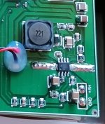
I am back with some interesting problem with LM5017 switching buck converter. In the past 3 years the chip just stopped working (it died). It happend 2 times compleately random while the controler (ESC) was powered at 80 to 90V sitting idle and motor stopped. In order to investigate i had left the thing powered on the table siting idle for about 2 hours every thing checks out fine the chip heated up to about 50deg (a bit to wam to hold the finger on it),the inductor also gets warm(220uH 1,2A rated), but all worked ok, so i moved on because i could not find any thing...
Yesterday while running a test with the prop on, at about 12A motor load, the thing stopped again, and found again LM5017 died, no smoke no puff no nothing chip looks new.
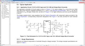
The schematic is the one presented in the datasheet, with type 3 ripple circuit, and the "D2" specified in datasheed to reduce load on the chip,(see shematic picture), my buck output volage is 14,2V but the "D2" is powered from post regulator 12V (lm7812) , in order to not exceed 13V on Vcc pin 6.
Now the current that i measured at the 90V input was about 120mA (with a DMM) , ESC idle + Display module connected (128x64 GLCD) , that is 10,8W does that mean that at buck output 14,2v i'l be about 10W and 1,42A ? (might sound stupid but up until this point i did not think of that :oops: ), because in that case it is a overload problem...
lm5017 sch.jpg
5017buck.jpg
 
Mihai_F said:
I am back with some interesting problem with LM5017 switching buck converter. In the past 3 years the chip just stopped working (it died). It happend 2 times compleately random while the controler (ESC) was powered at 80 to 90V sitting idle and motor stopped. In order to investigate i had left the thing powered on the table siting idle for about 2 hours every thing checks out fine the chip heated up to about 50deg (a bit to wam to hold the finger on it),the inductor also gets warm(220uH 1,2A rated), but all worked ok, so i moved on because i could not find any thing...
Yesterday while running a test with the prop on, at about 12A motor load, the thing stopped again, and found again LM5017 died, no smoke no puff no nothing chip looks new.
The schematic is the one presented in the datasheet, with type 3 ripple circuit, and the "D2" specified in datasheed to reduce load on the chip,(see shematic picture), my buck output volage is 14,2V but the "D2" is powered from post regulator 12V (lm7812) , in order to not exceed 13V on Vcc pin 6.
Now the current that i measured at the 90V input was about 120mA (with a DMM) , ESC idle + Display module connected (128x64 GLCD) , that is 10,8W does that mean that at buck output 14,2v i'l be about 10W and 1,42A ? (might sound stupid but up until this point i did not think of that :oops: ), because in that case it is a overload problem...
lm5017 sch.jpg
5017buck.jpg

You might have overloaded it but I have had plenty of these die and I definitely have not been overloading them at 16 and 20s. I have a 2r2 resistor, 85Vtvs diode and 2.2uF ceramics in front of my ones inputs... They still die.

I think the bottom line is that where other manufacturers are optimistic with ratings, TI simply lie through their teeth. They recommend it for 48V systems.

The 516x series isn't much better in my experience, and TI MOSFETs are rated 200A for the same package limit as others rate 120, and i know from first hand experience the legs rapidly fuse at this current. They have an appnote for those 100V FETs that says "excellent choice for traction vehicles, 200A rating, we used 36 of them to make a 48V120A inverter".

You might want to swallow hard and pay the premium for the 140V linear tech parts, or buy a dcdc module.

Il be designing them out of all my future devices. In fact I'll be avoiding absolutely all TI parts, I frankly trust them less than the Chinesium no brands.

Incidentally, there are fake 5017s out there but mine were direct from TI's web store.
 
Mihai_F said:
I scoped only the gate with the short ground spring directly on fet legs (like photo from few posts early), DUT is battery powered, there is no ground loop, only one probe was connected to DUT.
My main concern is that p-p Vgs on that ringing is 20,6V, that is no good, and some crazy 178Mhz bursts ringing(see the zoomed one)
I will calculated some snubbers, put them on and scope again.

What is does the double pulse test look like when you do it at low current, like 10-30A or at lower DC bus? I've found some device I've tested look like your scope shots at high current, however at lower currents and voltages there was oscillation. I never got to root cause, just wondering if you tested that scenario. I tried using some IRF200P222 which I think has dual dies vs the IRF200P220 which I think only has a single die.
 
Man, if you can make this work with a 7-speed cassette and still fit into 135mm dropouts, I would be highly interested in buying. A 20x2.5" tire size running from a 48V pack would top out at roughly 100 mph. It would be PERFECT for what I want to do, assuming everything works.

Awesome work. I will be eyeing this topic for updates. :bigthumb:
 
This is awesome. Just awesome. Flight is my next frontier in the summer. I started working with someone who is a paraglide/hang-glide instructor who is taking me up when it warms up here (rocky mtns)

I will def be contacting you. I wanna build a system not necessarily for take off, but temporary boosts if you can find a thermal for lift. People here just run off a mtn at 12,000ft so as far as takeoff im covered by gravity, i just think it would be nice to have the ability to bring you up a bit.
 
zombiess said:
What is does the double pulse test look like when you do it at low current, like 10-30A or at lower DC bus? I've found some device I've tested look like your scope shots at high current, however at lower currents and voltages there was oscillation. I never got to root cause, just wondering if you tested that scenario. I tried using some IRF200P222 which I think has dual dies vs the IRF200P220 which I think only has a single die.

I did try one at 50A, a bit less ringing amplitude, but did not save it.
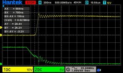
So here is shot at 24V and 100A pulse, with no snubbers and no ext Cgs, there is still a bit of ringing, but from what i read around here, that gate ringing might be because the source inductance (wires inside fet) that is why is in phase and amplitude with Vds ringing (at turn on), so the gate die inside the fet does not see that much voltage amlitude...
dso_01_01_00_36_11.jpg
dso_01_01_00_39_15.jpg
 
The Toecutter said:
Man, if you can make this work with a 7-speed cassette and still fit into 135mm dropouts, I would be highly interested in buying. A 20x2.5" tire size running from a 48V pack would top out at roughly 100 mph. It would be PERFECT for what I want to do, assuming everything works.

Awesome work. I will be eyeing this topic for updates. :bigthumb:

Please note that this was no designed for surface (road) use, it is not FOC, it does not have phase current sensing, without those things, you might not get the results that you need, like hard acceleration. The ESC will survive a hard acceleration from stand still, but it is not as efficient as FOC ESC-s. This was designed to turn a prop as fast as possible and be simple in construction and coding (SW), hence block commutation, at the expense of a few procents in efficiency, noise is not an issue since the prop makes a lot more noise than the motor, and waaay quieter than an 2 stroke ICE.
Now as for the power section only, that can be paired with a potent FOC brain, but that is another story...
 
rolocretaw said:
This is awesome. Just awesome. Flight is my next frontier in the summer. I started working with someone who is a paraglide/hang-glide instructor who is taking me up when it warms up here (rocky mtns)

I will def be contacting you. I wanna build a system not necessarily for take off, but temporary boosts if you can find a thermal for lift. People here just run off a mtn at 12,000ft so as far as takeoff im covered by gravity, i just think it would be nice to have the ability to bring you up a bit.

Thanks for interest and appreciation.
Just for temporary boost in altitude, and definetly takeoff, there might be to much weight to carry around when you want to do gliding, the gains from propulsion might be offseted by the losses of being heavier. When i did the performace calculations of my aircraft before i built it, the glide ratio of a 200Kg MOTW aircraft was about 12, but when added the propulsion system a 50Kg penalty now at 250Kg MTOW the glide ratio was reduced to 8,8 but now have a 45 min powered flight time (with take off up to 1000ft AGL).
So a reduction from 12 to 8.8 in glide, might be to much just to have 45min of powered flight reserve when you do soaring.
Before i will make this propulsion system available to public, i have to test it very very very well across temperature range, vibration, pressure (altitude), different continuous power settings, ect, and only if it is trouble free, and no abnormalities for a full year of flight, then i'm confident enough to say it is reliable, and you can trust it on takeoff and not quit working when you need it the most.
At the airfield that i'm testing it, i have a 900x300m grass strip, in witch my plane can take off land 5 times across 900m, so i have a lot of space for emurgency situations, and i can accept the high possibility of ESC to quit on take off during testing. My training in LSA was done with the mind set that there is a possibility of the motor will quit on me when i least expect it, so i always have to have a way out.
 
liveforphysics said:
Great job in your power bus packaging. You've got way above average electrical and thermal conductivity, and tight inductance. I'm excited to see how they perform, I may need to make or buy some for my own projects.

Been wondering, what commutation control would you pair this with/what do you generally use? Lebowski? VESC? ST/TI/infineon? Custom?

FOC, BLDC or other?
 
Back
Top