9C hall sensor/ wiring question?

Seya

10 W
Joined
Feb 27, 2012
Messages
81
image.jpgimage.jpg
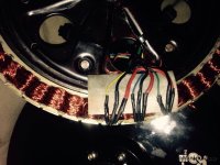
I just replaced all three hall sensors and the whole wiring harness.

Multimeter readings ( from the leads on the sensors themselves )

Are the following:

Yellow stays at 4.9v

Blue stays at 1.8v

Green alternates betweem 0 and 5v as wheel spins so it works fine.

The yellow and the blue arent working. These are brand new honeywell sensors.
I know my soldering is sloppy and you can see the glue was also not so pretty I'm doubting this is causing the problem.
As you can see in the picture the yellow Hall sensor is not in all the way. But it is reading a continuous 4.9 V. i don't understand things enough to know where to look next??

Any thoughts?
 

Attachments

  • image.jpg
    image.jpg
    103.6 KB · Views: 392
Thanks for your reply,

I spoke with a very well-educated electro mechanical engineer and they said the likelihood is either a wiring issue or heat damage hall sensors..

I guess I kind of could of figured that out myself but it was good to hear confirmed by someone in the know.

Since the wiring of these 9C motors is really poor quality I'm going to rewire it. And buy a better soldering iron and high quality solder.

I definitely did spend a lot of time trying to solder the leads and I'm sure that a lot of heat was transferred into the sensor.

I just don't know if it was enough to cause damage as the sensors should be able to tolerate a fair amount of heat.

I'll keep everyone posted on the results
 
Update:

I replaced all the wiring ( from controller to motor) with quality US-made wires.

Replaced all three hall sensors with brand-new Honeywell SS41 units.

Purchased a better soldering iron and took great care with all of my work.

Used gorilla glue for the whole sensors.


I have a similar problem. This time the yellow and blue hall sensors function properly..
But the green one still does not measure more than 2.3 V and does not respond to magnetism. I've put two brand-new sensors encountered the same problem..

Could it be the hall sensor circuit in the controller??

Little background is that I had a perfectly functioning hub motor controller and battery. I tried to enable regenn by jumping the white wires on the controller and hooking up the ebrake wires. this caused the motor not to work. And then all of a sudden did work and made a loud grinding sound..

Any thoughts would be really helpful as I've reached the limits of my knowledge
 
Yes, it could be a problem in the controller.

Easy enough to remove the controller from the equation. Rig a simple test circuit with external B+ supply 5-12V battery or clean power supply and a pull-up resistor around 10k Ohms. Voltage and/or resistance does not need to be exact - just in the ballpark.

Check this thread, scroll down a few posts and find my photos of a crude "test rig" which verifies the sensor operation without relying on the controller circuitry:

http://endless-sphere.com/forums/viewtopic.php?f=3&t=57053&hilit=

You could also merely buy an eBike tester which is a handy thing but for cheap & now, battery, resistor, magnet and DVM is pretty hard to beat.
 
why are the red wire and black wire in those pictures so huge?

why did you replace the hall sensors in the first place?

did you do any testing to determine if they had failed? what did you do to test?

how do you test them now?

is this the only thing you ever soldered and do you use 60/40 solder or the anti lead solder? why would it be so hard?
 
Back
Top