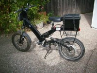
A2B Metro (Gen 1) Restoration and Upgrade

You mean rear, presumably?

I got one of these (125mm, I think) to replace that horrid standard A2B sprung unit:

https://www.ebay.com/itm/KS-A5-bicycle-soft-rear-shock-absorber-device-mtb-bike-rear-suspension-shock-New/283533376695?hash=item4203e7fcb7:g:tKcAAOSwPdhdGbBk

But will probably replace it with a 150mm unit, as I find with the extra weight of a rear battery pack (+ any luggage), there is still not quite enough travel/clearance to prevent the tyre contacting the inner fender etc over rough ground or big bumps.

;)
 
E-Glider said:
But will probably replace it with a 150mm unit, as I find with the extra weight of a rear battery pack (+ any luggage), there is still not quite enough travel/clearance to prevent the tyre contacting the inner fender etc over rough ground or big bumps.

Good to know as I plan on slapping 2 more battery packs on the rear. I'll look into 150mm shocks.

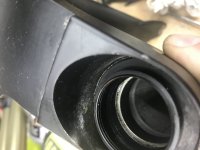
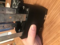
In the mean time, I've got the bike almost completely stripped down for sand blasting and repainting. However, on the fork arm, I can't quite figure out how to get the rubber seals off. These guys:

2021-02-07 14.12.34.jpg

Any advice here? I don't want to force it the wrong way and wreck them -- these look custom enough ruining them would be a one way street buying a new fork :/
 
Yes, although you will get a slightly higher rear ride-height with the 150mm unit, you should also be able to adjust it's air pressures to best suit your setup/body weight etc.

Sure, who knows whether A2B custom made their seals, or used an available 'off the shelf' unit.
I guess you could get some accurate measurements and research it further?
Failing that, I'd simply leave them in place and find some suitable tape to protect them (and the tube internals?) prior to blasting/repainting etc.

;)
 
chuyskywalker said:
In the mean time, I've got the bike almost completely stripped down for sand blasting and repainting. However, on the fork arm, I can't quite figure out how to get the rubber seals off. These guys:

Any advice here? I don't want to force it the wrong way and wreck them -- these look custom enough ruining them would be a one way street buying a new fork :/

No idea, buy why do you want to remove them?
 
PHEW UPDATES

To get the color removed, the parts were going to need an oven bath followed by blasting as the "paint" is actually a powder coat. So I attempted to remove the rubber grommets from the fork so it could be done. Failed, utterly. I think they are glued in or something. After ripping them out, the fork is ruined -- I mean, it would still work, but the mangle side would fill up with dust, gunk, and water in weeks and just get wrecked.

Shopped around for a replacement fork and discovered that the steerer tube for this is something of a freak-of-nature. At just under 13" long, it must have been a custom-for-this-bike made model because I can't find any after marker replacements that come even close to that -- no bueno.

At that point I was pretty much ready to throw in the towel. However, as this is a very old series bike, and I had previously been thinking about needing a way to source parts, and (hope of hopes) find an OEM internal battery, I'd been searching for used A2B Metros.

Lady luck smiled upon me and I found a listing for a second generation metro, local, in (basically) mint condition with just 650 miles on it. Snapped that up real quick. Not only did it have the v2 upgrades (controller NOT in motor) but also came with the rear panier rack and the rear battery! And both batteries still hold a charge. NUTS.
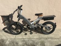
2021-02-13 14.19.44.jpg

So what did I do with this perfectly working bike? Immediately started stripping it down, of course! No 36v boat is gonna work for me, sorry. The new DD45 from Grin + wheel arrived, I mounted a new tire (only popped ONE tube, amazing), and got in on the bike. Had to swap out the 7speed for single speed as the dd45 is just, like, 5mm too wide for it to not rub, and I just don't feel like bending this arm.

Working with the Cycle Analyst / Phase Runner combo has definitely had some uphill battles.

For example: I was trying to use variable regen braking and whenever I pulled the brakes, POOF, total power loss and a blinking controller. I have the "throttle low voltage" set to 1v, "throttle hig" at 4.2v. Since that's the full range, I set the "throttle fault range" to 0. If you want to use regen braking, you have the phrase runner configures to understand that 0-.8v is an inverted range for braking strength. Yet, every brake activation faulted the PR and produced the message "voltage out of range". Now, this error kind of makes sense in that the range is 1-4.2 and the regen signal is not within those bounds, but the regen bounds ARE set, right? Well, there's a hidden gotcha: the "fault range" must cover the regen amount; in my case 1v so that the 1.0 to 0.0v values aren't "out of range". This is, imo, bad design on Grin's part.

After that hurdle, my next big todo was the phase runner/ca connection cord -- the plug does not fit through the Metro's internal routing channel. I ain't no scrub that's gonna just zip-tie it on the outside, so I painstakingly (man, these little JST molex things are a NIGHTMARE to pin) wired a ethernet cable (8 strands? Perfect!) to two ends of a CA extension cable.
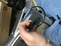
2021-02-14 19.44.53.jpg

Works great, and very glad I can hide most of it inside the frame.

I got throttle, brakes, CA, and a 3way switch mounted on the handle bars. I've got a few large items on the todo list through:

[ ] Two more battery packs (supplies arrived this week)
[ ] Parallel wiring setup for the 3 batteries (awaiting some breakers-as-switches)
[ ] Mounting the extra batteries and switches for them (3d printing time!)
[ ] Mounting the PR inside the frame
[ ] Rechain the bike for the single speed (??)
[ ] Fabricating new torque arms

That last one should be interesting. I nabbed a dimension sketch from another thread and will likely attempt to machine these at home from some steel -- should be a fun learning experience in which I ruin a few bits :D but a necessary one as all the original hardware is designed for a 12mm diameter bolt and the DD45 is the slightly larger 14, so nothing fits. I'll make at least two so I can reinforce from both sides.

Really feel like I'm getting somewhere at this point, very excited.
 
Slow going as I build the batteries and keep finding I need "just that one other thing".

What I've been working on...

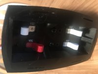
breaker-box-bottom.jpg
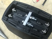
breaker box parallels.jpg
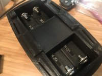
breaker box coverage.jpg
breaker box bars.jpg
breaker box wiring.jpg

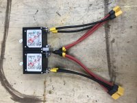
I printed and mounted up 4 breakers -- two batteries will feed into the rear ones, the accessories will come off the 3rd, and the fourth (50a) will feed the controller. The 3d print will attach where the controller used to be at the bottom of the bracket, and some metal strapping slips through the print to hold it on securely.

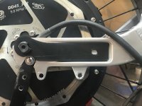
torque arm.jpg

I also spent about 8 print iterations getting the shape and size right for new torque arms ready. (The old motor is 12mm, new is 14 so they don't fit.)

phase runner mounting.jpg

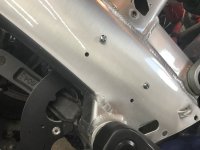
I drilled some holes in the chasis so that I can bolt mount the phase runner inside.

At this point, I did a test fit and realized I simply wasn't going to have enough space in the tube for the controller, breakers, a dc/dc converter for accessories, and (someday) some led lighting controllers.

So I decided to abandon the first battery pack, tear it up, and just go with two in parallel mounted to the rear. Kinda glad I did -- it'll work out a lot better, over all, and now I've got oodles of space to play with in the downtube.

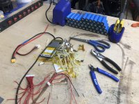
battery disassembly.jpg

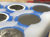
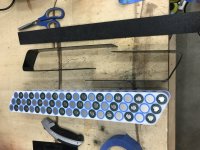
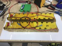
I spent a day or two messing about with trying to 3d print a better cell spacer/holder since I didn't want to wait for shipping, and had a particular setup in mind. It went -- ok, but I had an enormous amount of trouble printing in PETG, which is recommended to handle heating up batteries.

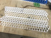
So I resorted to something a bit more reliable -- my CNC machine!

two sided nice.jpg
two sided bad.jpg

Here I tried to get really fancy and do some double sided milling so I could get that nice "sunken battery, caught edge" holder style. But, uh, I clearly didn't get things lined up very well and that kinda ruined them. So, I simplified:

holder after cut.jpg
holder processed.jpg

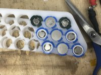
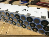
In the end, I just milled holes and the shape I wanted and ended up with some absolutely lovely single piece cell holders.

holder populated.jpg

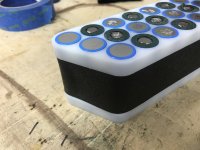
Populated with cells, these look pretty good, but something was missing...

abs wrap off.jpg
abs wrap on.jpg

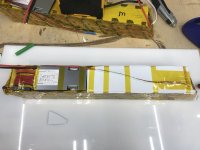
Ah ha! Cut down and bend some ABS 1mm sheet and now I've got some sushi packs. Nice.

....now for the really fun part.

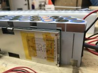
One of my pet peeves with BMS's is the absolute cluster fuckery of wires coming off them. In a 20s pack, that's 21 balance leads. And it's just a MESS. Plus, you often HAVE to cross the wires over because the bms and battery setup almost universally requires it.

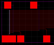
So I decided to do something wild about that....and designed a PCB to do distribution:

pcb-diagram.png
pcb-closeup.png

Here you can see how it's laid out, along with a close up. Because PCBs can have multiple layers, you can use a "via" to connect to a trace on the underside, carry it up across all the "wires" it would have to cross, come back, and ta da. Nice and neat!

Cost me about $30 all in, plus an evening or two of figuring out the software and getting the dimensions right. I was near dead certain this would be a loss -- I'd messed up the dimensions, or the traces were bogus, or you wouldn't be able to spot/solder onto the pads.

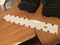
pcb on desk.jpg
pcb on pack.jpg
pcb holes and bms.jpg
pcb solderd up.jpg

NOPE

Works PERFECTLY. (Well, almost, it's a taaad bit short, but not enough to ruin anything.)

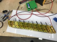
pack half welded.jpg

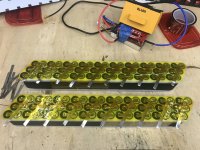
I made some pretty good progress on getting the cells welded up.

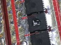
blown mosfet.jpg

Then disaster struck and my cheapo red welder blew a mosfet. Ah well, that's what you get for $35. I'll be picking up a kweld, I think.

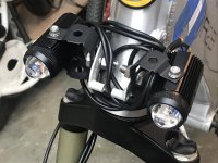
added lights.jpg

Until then, I'll work on some other things, like getting everything mounted into the tube, handle bars all wired up and neatened, and getting some headlights on that bad boy. (Which was kinda fun to drill that old headlight holder out and tap some m8x1.25 threads into it.)
 
Really beautiful work here.. thank you for sharing! :)

~ Maybe two securing bolts through the torque arm/plate? ;)

:bigthumb:
 
2021-03-12 19.27.10.jpg
Picked up a kweld after blowing out the cheapo and finished up the spot welding along with attaching leads.

2021-03-12 19.32.02.jpg
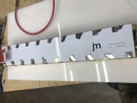
Here's the PCB laid out on the side. Came out mostly ok -- definitely a few things I would change if I were to iterate on it. For example:

  • Line up the landing pads with the negative cell ends so spot welding on the negative side is easier an safer
  • Make the landing pads a little wider to better account for slight variances
  • Enlarge the holes for the wires just a smidge

But it does work really nicely, so I'm still quite happy with it.

2021-03-12 20.21.31.jpg
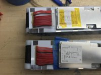
The two packs all wired.
2021-03-13 11.07.23.jpg
Add a little padding to keep that positive lead

2021-03-13 16.19.18.jpg
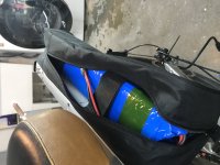
Wrapped up in shrink wrap and stuffed into a tripod bag that's been attached where the old battery tray used to slide on at. There's a piece of HDPE in the bag which I screwed through, and the battery is wrapped around that with 2 2" velcro straps.

2021-03-13 16.46.02.jpg
And, of course, there are two of them.

2021-03-14 13.22.35.jpg
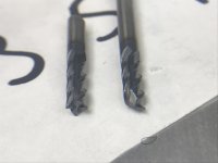
Finally, I tried to be cool and mill out some steel on my CNC to create new torque arms. As you can see, it did not go well. I killed three bits, and after pulling the upteenth steel sliver out of my hands I gave up on that.

2021-03-14 19.58.26.jpg
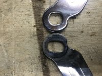
My backup plan worked out find, though. Since I've got two of these frames, I also have double torque arms, so I just filed these to fit the needed height of the new motor. Seems to work just fine. A little concerned about the extra material removal, but honestly, this bike frame itself is pretty sturdy and generally made with a motor in mind already anyway.

2021-03-14 20.41.35.jpg
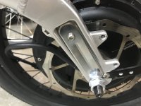
The non-drive side which normally doesn't have a torque arm. I drilled and tapped a compatible hole as well.

---

Only things left:

  • 12v dcdc for accessories
  • MiniPAS from Grin
  • Rear shock

All of these are currently in shipping boxes in various locations and, once I get them, should have me ready to install those, get all the wiring stuffed into the main body, put the chain back on, and that should be done.
 
fechter said:
Looking good. Did you solder the balance tabs onto the circuit board?
Nope, just turn down the E val to about 7.5 and it spot welds on. Killed an entire board testing out values :) But, I bought 5 for that reason. And to screw up a few times, which I luckily did not.
 
I know nothing about this.

A2B Metro and IZIP E3 Ultra Battery Replacement Ebike, 36v, 10.75ah
https://www.ebay.com/itm/A2B-Metro-and-IZIP-E3-Ultra-Battery-Replacement-Ebike-36v-10-75ah/324522165392?hash=item4b8f074490:g:y40AAOSw9jNgTviQ
 
chuyskywalker said:
Nope, just turn down the E val to about 7.5 and it spot welds on. Killed an entire board testing out values :) But, I bought 5 for that reason. And to screw up a few times, which I luckily did not.
Interesting. I haven't had much luck with spot welding to circuit board copper. It would just blow a hole in the copper or not stick.


A2B Metro and IZIP E3 Ultra Battery Replacement Ebike, 36v, 10.75ah
https://www.ebay.com/itm/A2B-Metro-and- ... Sw9jNgTviQ

That guy will probably sell a lot of those. From A2B, when they were available, the replacement battery was something like $850.
 
Wow amazing skill and content mate. I guess you need to change the title now. What are your plans for the down tube now then? Battery in the back whilst easier and more convenient does it not tend to cause a tail wag feeling don't you feel? I know you ain't no scrub but what about a battery on top of the downtube? Current I have a 50ah 18s lipos strapped to the downtube, whilst not pretty it handles like a motorbike, feels planted and reduces wheelies. I'm sure with your skills you could come up with something more visually pleasing.
 
fechter said:
Interesting. I haven't had much luck with spot welding to circuit board copper. It would just blow a hole in the copper or not stick.

2021-03-19 19.55.29.jpg

Testing with the broken red welder and the kweld.

---

Audisport09 said:
What are your plans for the down tube now then?

Gonna hold all the aftermarket electronics now. Phaserunner, breaker switches, dc/dc converters for accessories, and likely and LED lighting controller at some point.

Audisport09 said:
Battery in the back whilst easier and more convenient does it not tend to cause a tail wag feeling don't you feel? I know you ain't no scrub but what about a battery on top of the downtube?

The bike was designed to have a fairly weighty battery in on the rear rack, so we'll see how it goes. I'm not really worried about wheelies overall, to be honest, as I intend to tune this as a cruiser more than a power-sport setup. Max battery amps in the 40A region.
 
I have hundreds of miles with a big, heavy battery on the rear rack, including a lot of off road hill climbing, etc. and the handling is not too bad. On the street, I don't even notice it.

100_0548.jpg
 
fechter said:
I have hundreds of miles with a big, heavy battery on the rear rack, including a lot of off road hill climbing, etc. and the handling is not too bad. On the street, I don't even notice it.
Are those tires the MMG's?

If so, I have a question I'd posted over in your Metro thread:
https://endless-sphere.com/forums/viewtopic.php?f=6&t=50590&p=1616736&hilit=tire%2A#p1616736
 
Yes, that is the post I was replying to in your thread. It has some details, but none of them answer the question(s) in the post I linked. ;)
 
2021-03-27 18.30.16.jpg

It goes! Took it out for a spin this evening around the block. Definitely gonna need to do some adjustments to the CA settings, but it's solid.

Had a small run in with the "30-90v -> 12v dcdc" letting out the magic smoke at 84v, but replaced it with another that does work.

Also, was wondering why I was only hitting a top speed of 30mph -- forgot I left it on 20A limit mode, oops :wink:
 
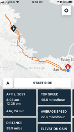
2021-04-02 12.58.00.png
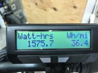
2021-04-02 12.28.48.jpg
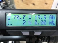
2021-04-02 12.28.34.jpg

Took the bike for it's first real long range break in ride; found out a few things:

  • The phase runner is choked for air flow and was routinely pulling me down to something like 6-10A battery power. I'm 99% certain it's thermal rollback on the controller as I didn't have any CA3 power limiting factors at play, and the motor was only at 50C (where the thermal rollback on the CA3 doesn't even start till 90C).
  • I used the original 7spd shifter to hold the chain in place for the single speed freewheel -- my hack to do so gave out half way back and so it was throttle only all the way back.
  • The single speed gearing is 110% useless over 10mph
  • The freewheel is noisy as bananas -- when it was disengaged, the bike was so much nicer without the constant clicky noise. I'm strongly considering just ditching the pedals and drive train and swapping to pegs (yes, yes, not a "bike" any more, I get it, let's not rehash that debate)
  • I lost a screw on the rear fender and found one of the rear axel nuts slightly loose -- yikes! Added locktite to the fender bolts and lock washers to the axel nuts and tightened better.
 
Back
Top