Adding CA-DP connector to non-CA-DP compatible controller

I understand this idea. Could this method be applied to a TK15 coulomb counter? Link

Of course, the TK15 can’t be used with the throttle and speed sensor. I’m thinking that the TK15 can have only the B +, B -, RS+, and RS- from the controller as described above. I believe that the TK15 RS is “Resistive Shunt”. Has anyone else done this? I can’t find much about this method.
 
As long as the meter you intend to use has an external shunt that wires into the battery negative, then you can wire it up to a "CA connector" on a controller, and use the controller's internal shunt (that is also wired into the battery negative)...but this only works accurately if the meter has a calibration option to set it up to match the actual shunt value.

If it can only operate accurately with the shunt it comes with, or with a specific value of shunt, and that isn't the same resistance as the one in the controller, it will not give correct readings for anything based on current (A, Ah, W, Wh, etc). If you know the proportion (ratio) between the controller shunt and the correct shunt, you can simply do math everytime you use a reading from the meter to calculate the actual readout, but that's kind of a PITA.
 
I see. Ok. Thank you. My aim was to use the controllers internal shunt and avoid using an external shunt. To use less space. The TK15 did come with its own shunt. I’ll wire that in as noted in the instructions. The TK15 works great. I was just hoping to consolidate things.
 
I see. Ok. Thank you. My aim was to use the controllers internal shunt and avoid using an external shunt. To use less space. The TK15 did come with its own shunt. I’ll wire that in as noted in the instructions. The TK15 works great. I was just hoping to consolidate things.
As long as the shunt resistances are the same, or the meter can be calibrated to the shunt you want to use, then you can.
 
As long as the shunt resistances are the same, or the meter can be calibrated to the shunt you want to use, then you can.
I checked the manual for the TK15. You can’t input shunt resistance. I’ll get my ohm meter and measure its shunt resistance and compare it to the controller shunt. I don’t imagine that they will be exact, but maybe they will be close enough to accurately read. Or, I’ll just use the included shunt. That’d be the easier way, but I want a cleaner install. :)
 
I checked the manual for the TK15. You can’t input shunt resistance. I’ll get my ohm meter and measure its shunt resistance and compare it to the controller shunt. I don’t imagine that they will be exact, but maybe they will be close enough to accurately read. Or, I’ll just use the included shunt. That’d be the easier way, but I want a cleaner install. :)

Impressed. You must have a really good ohm meter.
 
Probably not, unless you have a constant-current source you can use to measure the voltage drop across the shunts.

The shunts are usually a thousandth of an ohm or so, so these meters can't tell the difference between that and just the meter lead resistance.

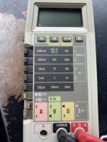
I have one of the same model (or at least series, the 8060A) meter as you've pictured, as well as the 77-IIIA, and neither one can read any shunt I've tried (or motor phases, etc). I have the DE5000 and it can barely read shunts and phases.
Like this one


But with a constant-current source connected directly across the shunt, you can measure the current while measuring the voltage drop across the shunt and divide those two to get the resistance via ohm's law. (in this case, the Vulture flying over the Anteater tells you the size of the Ostrich. ;) )
 
Last edited:
Back
Top