Adding halls to BLDC motors

Ecyclist said:
It is for 63mm motor. I need that board for my second 6355 2400W not sensored motor.

Yeah 63mm is too small for anything I'm likely to build. An 80mm stator is about all the smaller I'm likely to go for now. I'm mostly trending towards bigger and bigger EV's. I probably wouldn't know what to do with a 63mm motor except to put it on a quad copter.
 
A quad copter with four 63mm outrunners will make a chopper out of hell. You may start to think about government contracts. :D
That is a beauty of DIY. You can build whatever you dream out.
 
Ecyclist said:
A quad copter with four 63mm outrunners will make a chopper out of hell. You may start to think about government contracts. :D
That is a beauty of DIY. You can build whatever you dream out.

I think I'd go bigger and make an octo out of these motors. Actually what I'd like to do sometime is build an actual people carrier. I'd want it to lift it's weight plus 350 pounds at least. I've seen a few people out there post videos on youtube that did essentially that. Some people used gas engines which sounds horrible to me. I suppose if you could accurately govern each engines power output, it might be OK, but even then it would be very loud and stinky as hell. Realistically I'd use large outrunners...something in the 18kw+ range and then build an octo. The battery pack would be huge and the likelihood of dying while riding my EV would go up significantly and I couldn't ride it just anywhere so it would be an expensive toy that had very limited uses. BUT!!! How cool would it be to sit down in your own octo and fly to work or where ever!!!? I'd probably do 4 booms. Each boom would have 2 motors on it. Since my life would now be on the line, the whole thing would need to be able to fly on 4 motors or one per boom. Also I'd add a parachute so that if things did go south, maybe I might survive a crash landing.

Anyway that has zero to do with adding halls to motors!

I tried out my C80100 yesterday and the new halls made all the difference. The motor runs so much smoother now and the runaway throttle issue I was having is gone too. good halls...even known good chinese ones are better than unknown quality supposedly name brand halls that may or may not work.
 
I tested resistance of hall board components and on R1 thru R6 I'm getting from 103 to 105 ohms. These little guys are marked with number 101. Maybe they are resistors after all. I can't tell much about R7 and C1. I have a couple friends who sell industrial measuring tools. I will ask them to take a look. I will get to the bottom of this sooner or later.
 
Yes, 101 stands for:
First digit 1
Second digit 0
Multiplier 1 (Can be taken as the number of zeros to add to the first two digits)
So, 1, 0, 0 which is 100ohms.

For example 104 would be 100K ohms.
333 would be 33K ohms.
 
Altair said:
Yes, 101 stands for:
First digit 1
Second digit 0
Multiplier 1 (Can be taken as the number of zeros to add to the first two digits)
So, 1, 0, 0 which is 100ohms.

For example 104 would be 100K ohms.
333 would be 33K ohms.

What Altair said...those are resistors and you measured them. Caps don't "meassure" on the ohms setting on a DMM. Interesting. I'd really like to see a schematic of that board to be sure what the resistors are doing. I'm guessing pull-up, but what's the point since the controller does that already and now the halls have to work overtime to overcome 2 sets of pull-up resistors to pull down to ground. What's the point of that? Halls typically sink 30 mA so you can very easily overcome the hall output. 30mA is about what a lithium watch battery outputs..or enough to run a small LED. You probably can't power the LCD on your watt meter or CA with 30mA. That's probably less than the standby current of your motor controller when it's turned off.
 
So, I talked to my friend today and he thinks, and it all makes sense to me, that C1 is a capacitor that helps to keep 5V noise free and R7 is a thermal resistor. R7 is connected to white wire and that is labeled as a temp sensor. That was fun.
EG you most likely have the same board but bigger in your APS motor.
 
Resistors won't be necessarily be pull-up resistors.
They can be used in series with a capacitor to ground to form an RC filter.
 
Altair said:
Resistors won't be necessarily be pull-up resistors.
They can be used in series with a capacitor to ground to form an RC filter.

True, but where's the caps to make the RC network?
 
Altair said:
Hasn't someone said that there were resistors and capacitors on this board?

There is a single cap across 5v to ground, but no other caps. Everything else is resistors. That does not an RC network make.
 
good halls...even known good chinese ones, are better than unknown quality supposedly "name brand" halls that may or may not work

I agree completely. How many times have we seen a project that costs a lot of money, effort, and time be derailed and require weeks of trouble-shooting, only to have all the problems disappear when the builder replaces all three halls with quality authentic $3 units.
 
spinningmagnets said:
good halls...even known good chinese ones, are better than unknown quality supposedly "name brand" halls that may or may not work

I agree completely. How many times have we seen a project that costs a lot of money, effort, and time be derailed and require weeks of trouble-shooting, only to have all the problems disappear when the builder replaces all three halls with quality authentic $3 units.

I never use so called name brand or "high quality" halls. I have in the past, but then as usual I test everything before it gets put in place and I still had some that were bad. As a result, I just buy the cheap chinese ones and of course test everything. I expect I will get failures from either source so why spend $3 for a hall when I can buy 20 cheap halls for $3 and get the exact same results...after testing all of them. So far, even after a couple of years of use, I have not had a single cheap hall fail. That's all the more I expect out of expensive halls so I'm going to call that just as good for lots less money.

The real lesson to learn here is...test the halls before you put them in the motor no matter how much you paid for them or where they came from.
 
Another thing to do is always use ESD precautions, to keep from damaging electronic components with static electricity. ESD can cause damage that doesn't even appear until later, when the component is in use and stressed a bit, then it can just act wierd rather than outright fail.

ESD is probably the cause of most components that "don't work".

It isn't always the end-user that damages them, either; sometimes it's the middleman, distributor, etc.
 
amberwolf said:
Another thing to do is always use ESD precautions, to keep from damaging electronic components with static electricity. ESD can cause damage that doesn't even appear until later, when the component is in use and stressed a bit, then it can just act wierd rather than outright fail.

ESD is probably the cause of most components that "don't work".

It isn't always the end-user that damages them, either; sometimes it's the middleman, distributor, etc.

Yes good point! I don't think most people think about static discharge very much. My electronics bench is grounded and my soldering station is too. Lots of folks don't think about how they handle motherboards and other computer parts. They just pull them out of the ESD bags and most of the time they get lucky and things are OK for a while. I'm very much aware of static discharge.

On a side note to ESD...lots of people plug in their EV's to their batteries and get that big inrush spark that scorches connectors and possibly fries components. It's essentially an ESD discharge, but with lots of current. It will cause damage. I always tell people to precharge before connecting up the power.
 
I recently got a Revolt RV-100-Regular outrunner.

The gaps between the stator teeth are very narrow. Since this motor has an even number of stators, that's where the halls need to go. A 41F hall has to sit back at least 4mm from the stator faces to fit. That's how Revolt mounts them and I've read reports of people having issues with this. I don't like grinding into the stator teeth. It risks a short between laminations and the possibility of accidentally damaging a winding. I purchased some AH175 SMD halls which just fit in the gaps between the teeth.

RV-100-regular%20stator_1.jpg


I had 26 awg teflon wire and figured it would be fine enough for soldering to the halls. NOT the case! It's nearly as large as the hall. I've ordered 30 awg teflon in 5 colors.

hall%20wiring%20failure.jpg
 
This is coming soon...thought I'd add the post now since I'm here.

Halls will go between the stators since this motor has 24 teeth. However, there's 2 stators and I need to get the armature off to get at the other one. I think 41F halls will just fit in these gaps between the stators and be flush with the surface.

2018-08-15%2012_11_20-3031-001%20top%20stator.JPG%20-%20Windows%20Photo%20Viewer.png


3031-001%20top%20stator.jpg


3031-001%20armature%202.jpg
 
The left 2 halls are soldered to 28 awg wire and it is way too large for soldering to these tiny halls. Also space between the stator teeth is very tight. I needed thinner wire for soldering to the halls no matter what. I bought some 32 awg teflon wire and that worked well. And that's what the right most hall has on it. With tiny parts like this it is very easy to linger too long with the soldering iron and overheat the hall. To avoid this, I'd dip the soldering iron tip in a blob of solder and then in flux to get the solder clinging to the tip very clean. Then I'd hold the wire end to the hall leg and touch them both quickly with the solder on the tip. Instant bond and not too much heat.

hall%20wiring%20failure.jpg


The halls are about 1mm x 1.5mm with legs that are maybe .2mm. I really needed the thinnest teflon wire I could find. As it turns out 32 awg is perfect for the job. Here's a few pics of soldering wires to those micro small hall legs. Good solder is the only thing to use here. Cheap solder would not have solidified nice and smooth like this or held such a tiny connection reliably.

SMT%20halls%201.jpg


SMT%20halls%202.jpg


SMT%20halls%203.jpg


SMT%20halls%204.jpg


SMT%20halls%205.jpg


This is the halls all shrink wrapped and ready to install. They are a perfect fit in the gaps in the stator teeth. I'll use thermal glue to secure the halls in place. The halls will not have a to sit deep inside the stators like how Revolt installs them. They use 41F's which of course are too large for the gap between the stator teeth. The red wires will get spliced together and so will the black wires after all the halls are in place. The 3 signal wires are about 10" long. I'll heat shrink all the wires together before they exit the motor.

SMT%20halls%206.jpg


Last time I installed halls in a motor, I used JBweld. That pretty well makes them permanent parts of the motor. I didn't want to do that again if I ever had a hall go bad. This time I secured them with thermal glue. It gets fairly hard, but can be picked away from the stator with out too much trouble. This makes it possible to replace a hall if or when one dies. It secures the halls sufficiently to keep them in place. I can tug on the hall wires and the halls don't move. It's hard to see in the images, but the top surface of each hall is flush with the stator face.

Halls%20between%20stator%20teeth%202.jpg


Halls%20in%20motor%201.jpg


Halls%20between%20stator%20teeth%203.jpg


I don't know how Revolt brings out the hall wires. The phase wires are a fairly snug fit in their holes. There was no spare room for the halls to come out. I picked the phase wire hole closest to the junction of the three halls and carefully nibbled away the aluminum until I could make this opening for the hall cable.

Halls%20in%20motor%202.jpg


A couple extra layers of heat shrink ought to protect those tiny wires from any abrasion and it all fits inside the skirt bearing. Some strategic placement of thermal glue and a few zip ties secure all the hall wires so nothing can move or rub.

Halls%20in%20motor%203.jpg

Halls%20in%20motor%205.jpg
 
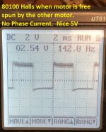
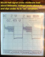
I have an external hall board on my 80100 motor. I get some weird skips in power delivery when I hold a steady rpm under load. I finally got a chance to hook a scope up to them and get some idea of what the signal looks like. I'm spinning the motor with a hub motor mounted to the same swingarm that the 80100 is on. Its my makeshift Dyno and allows me to spin the motor under a wide range of load conditions. The Hall signal looks way cleaner when I free spin the motor compared to when I load it. I'm using a Lyen 12fet controller to power it. I noticed the voltage in the on position under load dips below 4v. Do you all know how much voltage range or noise one of these controllers can tolerate? Do I need to add pull up/down resistors or capacitors to smooth this out so its cleanly above 5v when they are in the "on" state? Could be any number of things causing this hiccup but the halls seemed like a good place to start looking.

This is the testing setup.
View attachment 2

Nice clean signal from the 80100 halls when they motor is unpowered and being spun by the hub motor via the chain.
Halls free spin.jpg

Under load the signal gets much uglier. I'm wondering if the field from the stator is inducing too much noise at the sensors. Admittedly I have no idea how much noise is too much. I get basically the same signal when I am running the 80100 at 800-1000 watts as I do when I set the 80100 to regen and drive a similar amount of watts with regen. Either way, fielding the stator windings with current in either direction produces this noisy signal compared to no load.
hall 3.jpg

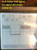
This last pic is the hall signal from the 9c hub motor for comparison. It also seems to go under 4v in the on state but still looks cleaner and less noisy to my untrained eye (I borrowed the scope and have about 1 min of training on it)
Hub Halls.jpg
 
5V dipping when running is not good. any idea what is loading down the 5V Dc-Dc in the controller?
An external cap on the hall wires at the motor would help clean up the 5 volts. You'll want a 100uf electrolytic and a 10uf tantalum in parallel at the motor.

However, will that clean up the hall signals? I doubt it. I bet your hall signals are cleaner because you don't have RF interference form the motor phases.
 
Quickie post...

I for whatever reason never posted about actually making up a hall harness for a motor. I commonly build the hall harness in the motor, but I also do it this way too.

I used teflon wire so it can hold up to whatever heat is happening in the motor. I used real SS41F halls bought from Mouser, NOT chinesium halls bought on ebay. Reliability is key here and the chinesium ones may or may not last. Also, getting halls that actually work is sometimes hit and miss. It's better to just buy legit halls from a legit source. I've tested chinese halls, installed them in a motor and a few days later they go bad. GRRR! Yes they cost 1/20 the money, but there is really good reasons for this!

The first thing I did was cut sections of the smallest size heat shrink I had in red, black and yellow. They are about 1/8" shorter than the length of the hall legs. I shrink these sections down and this makes them just about the right size to slide over the hall legs. I now have via color the leg pinouts. Red is +5v, black is ground and yellow is signal. There's no point cutting yellow blue and green heat shrink for the signal leg since I have no idea at this point which hall is which. Also the actual color of the signal wire is irrelevant. They will go into the motor 120 degrees apart and ONLY after you try out the halls with the phases do the three signal colors actually matter in any way.

I tinned the ends of the hall legs and the wire ends that will solder to them. This makes solder flow virtually guaranteed between the leg and the wire end. I cut 4 lengths of red and black at about 3" long. These will go to 2 of the 3 halls. The third hall will get red and black soldered to it that are long enough to exit the motor. At 3" from the hall, I strip off a short section of the insulation form these 2 longer wires and solder on the red and black wires from the other 2 halls.

Once all 3 wires are soldered to a hall, I then slide heat shrink over the solder connections and over the heat shrink already on the legs. Chances of a short are virtually impossible. I then use a slightly larger diameter piece of heat shrink over the hall and part way down the legs. This keeps the hall legs from bending and flexing independently so they won't break from vibration in the motor.

All electrical connections get covered in heat shrink.

Motor%20hall%20harness%201.jpg


I didn't show it in this image, but I also color the face of the hall so when installing them I don't put them in backwards. When done all wires are cut to the same length and the 5 ends tinned. I left about 12" of length. This will be more than enough to get the wires out of the motor with lots of extra length too.

Motor%20hall%20harness%202.jpg
 
Overall the signal seems to avg 5v if im reading this correctly. The on and off time looks about the same and the upper left reading is around 2.5v. Im assuming that is the avg between 5 and zero. Its just the shakey oscillations around the 5v line that im wondering about. How flat should that line be?

Also, if I add some caps in an attempt to smooth this would I be adding them to the output pin of each hall or just on the shared VCC leg?

This is my first time playing with an oscilliscope. Its cool that I have some data now but I sure wish I knew what it was supposed to look like.
 
I would add the caps on the supply line of the halls, between + and -.
0.1 uF would be OK. Maybe one close to each Hall, if you have a lot of noise, otherwise a single one for the 3 halls will be OK.
 
So basically just add the cap like the one outlined in red on this diagram? What is the math used to determine the value of these caps and pull up/down resistors in this circuit below? Is there any harm in adding the bypass cap between output and ground as well?

Also just to check my understanding here:
  • Is the idea of the pull up resistor to add a second parallel pathway between V+ and the output to get the output closer to V+ just in case there was some voltage drop somewhere?

  • Does this raise the value of the output in the off state as well?

  • Is a pull down resistor just the same idea but between output and ground such that it would lower the voltage of the output signal in both states?


Thanks
 
DanGT86 said:
Is there any harm in adding the bypass cap between output and ground as well?

Yes, if the capacitor value is too large, it will greatly slow down the switching time. A properly sized cap will take out most of the PWM noise without slowing down the transition too much. With a scope, you can test the effect of various cap sizes. My guess would be more like 0.01uF, but I have never tried this.

Some of the noise you are seeing might be artifact from the scope probe and not really there.

The SS41 and similar hall switches can only pull down, not up, so you need the pull up resistor. If you place a resistor to ground, it will form a divider which would limit the high value. You don't want to do this normally.
 
Back
Top