Adding halls to BLDC motors

DanGT86 said:
This last pic is the hall signal from the 9c hub motor for comparison. It also seems to go under 4v in the on state but still looks cleaner and less noisy to my untrained eye (I borrowed the scope and have about 1 min of training on it)
Notes:
1) That could be your scope probe picking up some of that through coupling to the power signal. So it may not be all real.

2) That could also be the phase (power) line coupling to the Hall sensor lead which is real. A stronger pullup will help there. Also, an RC filter might help on the signal itself. For example, a 100 ohm in series, and a .01uF from controller pin to ground (at the controller end not the motor end) would give you a filter at 150KHz which should help.

3) It might be noise on the 5V line but probably not. A 1uF or so ceramic (NOT electrolytic) cap between +5 and gnd at the Hall sensor may help there.
 
billvon said:
DanGT86 said:
This last pic is the hall signal from the 9c hub motor for comparison. It also seems to go under 4v in the on state but still looks cleaner and less noisy to my untrained eye (I borrowed the scope and have about 1 min of training on it)
Notes:
1) That could be your scope probe picking up some of that through coupling to the power signal. So it may not be all real.

2) That could also be the phase (power) line coupling to the Hall sensor lead which is real. A stronger pullup will help there. Also, an RC filter might help on the signal itself. For example, a 100 ohm in series, and a .01uF from controller pin to ground (at the controller end not the motor end) would give you a filter at 150KHz which should help.

3) It might be noise on the 5V line but probably not. A 1uF or so ceramic (NOT electrolytic) cap between +5 and gnd at the Hall sensor may help there.

Be careful with a "stronger" pull-up resistor. 41F halls (or just about any hall used in BLDC motors) are current sink devices. They have to overcome the "pull up" current from the resistor to "pull down" to 0v and they can only sink 20mA. This is a very small amount of current and easily overcome with a "stronger" pull-up resistor.

Where are your halls located? If they are on top of the motor and then the hall wires have to pass through the stator to exit the motor, this will induce the most noise on the halls. Halls placed as close to the exit of the motor as possible is the best.

Are your halls placed where they directly face the magnets? It's fairly common that the halls are offset from the magnets so they don't directly "read" the faces of the magnets as they pass by.

How close are your halls to the faces of the stator teeth? You want the hall faces flush with the surface of the stator teeth. If they are inset some, this will diminish their ability to detect the magnets.

The hall at the bottom of the stator is very close to the exit of this motor, It is also placed flush with the face of the stators. It's in the stator so that magnets can pass directly in front of it. IE: It will get the best possible "signal" from the magnet with the least amount of interference. The hall on the board is above the stator so it doesn't actually face a magnet directly. It's inset from the stator faces by about 1/4". It's wires have to pass down through the stators to exit the motor. This is far less optimal. It works, but it's not as "clean".

C80100%20blue%20hall_zpsprpkdhfy.jpg


This is optimal hall placement. The hall cable immediately exits the motor. The halls are directly exposed to the faces of the magnets and they are flush with the faces of the stator teeth.

3000%20watt%20inrunner%203_zpsmvt4fqub.jpg


This is pretty good with the exception that the halls are not directly facing the magnets, but it's as close to the magnet faces as I could get. It does meet the other 2 goals: At the face of the stator teeth and the cable exits in the shortest path.

Astro%20Flight%203220%20halls%202_zps8g1lstdm.jpg
 
ElectricGod said:
Be careful with a "stronger" pull-up resistor. 41F halls (or just about any hall used in BLDC motors) are current sink devices. They have to overcome the "pull up" current from the resistor to "pull down" to 0v and they can only sink 20mA. This is a very small amount of current and easily overcome with a "stronger" pull-up resistor.
Well, it only really has to be able to pull it down to .8 volts (TTL threshold) for cheap controllers. A 10K resistor is a common pullup; at 5 volts that means a .5ma draw. Dropping it to 1K means an increase to a 5ma draw; still well within the spec of the device. And it gives you 10x the noise rejection.
Where are your halls located? If they are on top of the motor and then the hall wires have to pass through the stator to exit the motor, this will induce the most noise on the halls. Halls placed as close to the exit of the motor as possible is the best.

Are your halls placed where they directly face the magnets? It's fairly common that the halls are offset from the magnets so they don't directly "read" the faces of the magnets as they pass by.
Although Hall placement is of course important, it looks like in this case he's getting a good signal. It's the noise he is seeing when the Hall is off that is likely problematic.
 
Halls are external so they are reading through the motor can using one of these boards. I routed the wires away from the phases and main power input wires just as an added measure. That didn't seem to change anything.
http://e0designs.com/documentation/hall-effect-sensor-board-adapter-installation/
sensboard_asm10-300x225.jpg

The Halls are ATS177. Looks like they can sink 25ma and have some built in noise reduction features already as well as temp compensation. Is this standard for ebike motor hall sensors?
https://www.diodes.com/assets/Datasheets/ATS177.pdf

I'm also not totally convinced the halls are the source of my intermittent stumble. It was just a good place to start looking and since I borrowed the scope I actually had some real data to have you guys look at.

In the interest of learning I stopped by the electronics store today and picked up a range of capacitors from 0.01-1.0uF. I'm curious if they have any noticeable effect on the noise.

The reviews from other board members running RC motors with cheap Ebike controllers have been mixed over the years so I wouldn't be surprised if its something else causing the stumble. There is a CA3 controlling the throttle as well so I might be briefly hitting a programmed current limit spike. There is a lot of factors yet to eliminate.

I'll report back with the results from the capacitor tests.
 
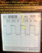
Caps worked out well. In my original test a few posts back I had the leads reversed at the meter so my noise was in fact in the off state. :oops:
If the controller threshold is .8v then I can see where this noise was easily getting there.

I started with just one cap from the pos to neg feed shared by all the halls. That didn't seem to make much of a difference. I then experimented with a variety of cap values from .001uF to .1uF. on each hall between the output and the +5v. The .01uF is the sweet spot for sure! I was happy to actually see the change on the scope too. The 1.0uF cap caused the transition of the on-off state to be a diagonal line rather than vertical on the scope. Makes sense. Turns out the maker of the board recommends smoothing the signal with .1uF caps.

Unfortunately the stumble is still there and now I noticed that one of the halls doesn't produce a clean signal at all now. I feel like I checked all 3 last time but now its being problematic. I'm going to try and source a new sensor or 3 if I can't figure out which one I have. I assume it's bad to have 1 mismatched to the other 2 right?

I also noticed that I'm only getting 4.3 volts now instead of my 5 the other night. The avg is lower on the scope now as well. It was 2.5v the other night and now its 1.8v even when I check it without the caps. Maybe the problematic hall is pulling it down. Maybe it's because I was measuring reverse polarity the other night with the leads reversed and the wiggle is on the 0v side so i'm getting negative values whereas it was all above 0 last time.

Anyway, here is my data. Thanks again for the instruction guys!
View attachment 1
halls with caps.jpg
 
That looks pretty clean with 0.01uF.

You could try disconnecting the suspect hall and see if the supply goes back up to 5v.
 
Looks like the whole 5v bus is 4.33 everywhere I check. I rebuilt the hall connector with fresh pins and good crimps. That one hall in question wont read a good signal with the scope in auto. The other 2 will. When I manually set the time in the scope they all read nice and clean with the caps. I'm thinking its probably ok.

I need to ride this thing to see if the miss/stumble is gone now. I dont hear it but it was very apparent while riding before.
 
Hi all

I have recently made a Lebowski board to run Leaf EM61 motor off 360Vdc. https://endless-sphere.com/forums/viewtopic.php?f=30&t=36602&start=1700#p1456329
It can run sensorless quite good, but i am concerned i will have trouble starting a car uphill. Leaf motor has resolver at the back. This is not much use to this controller as it needs comutation encoder. I used your discusson here to estimate how far i must place sensors. I can have direct access to rear motor windings. Motor is 48tooth, 8pole 3phase BLDC motor. First i gor 120deg placement at 16 teeth.
I was thinking if i could change my calculation of sensor placement from 120deg into 60deg would that be ok still
Instead of calculation for placement sensors: 360/48 = 7.5deg per tooth, 120deg/7.5deg = 16 teeth apart
I would use placement of sensors: 360/48 = 7.5deg per tooth, 60deg/7.5deg = 8 teeth apart
Heh, maybe i could get away with placement per 30deg? That would then be 4 teeth apart?

Can you estimate if that would work? It would make my cables quite a bit shorter inside motor.
 
arber333 said:
Hi all

I have recently made a Lebowski board to run Leaf EM61 motor off 360Vdc. https://endless-sphere.com/forums/viewtopic.php?f=30&t=36602&start=1700#p1456329
It can run sensorless quite good, but i am concerned i will have trouble starting a car uphill. Leaf motor has resolver at the back. This is not much use to this controller as it needs comutation encoder. I used your discusson here to estimate how far i must place sensors. I can have direct access to rear motor windings. Motor is 48tooth, 8pole 3phase BLDC motor. First i gor 120deg placement at 16 teeth.
I was thinking if i could change my calculation of sensor placement from 120deg into 60deg would that be ok still
Instead of calculation for placement sensors: 360/48 = 7.5deg per tooth, 120deg/7.5deg = 16 teeth apart
I would use placement of sensors: 360/48 = 7.5deg per tooth, 60deg/7.5deg = 8 teeth apart
Heh, maybe i could get away with placement per 30deg? That would then be 4 teeth apart?

Can you estimate if that would work? It would make my cables quite a bit shorter inside motor.

Yes I think you got it right with 4 teeth seperation.

One of the better resources for Hall sensor placement.

http://mitrocketscience.blogspot.com/2011/08/hall-effect-sensor-placement-for.html

The key thing to remember is the motor needs to be commutated at 120 degree electrical. So the Leaf motor has 4 pole pairs so there are 1440 electrical degrees for every 360 mechanical. Given 48 teeth you have 1440/48 =30 degrees electrical per tooth so spacing the sensors 4 teeth apart gives you 120 electrical seperation. The sensor placement must start in correct slot and the article gives guidance on that. It pays to scope bemf versus hall outputs in any case just to confirm you got it right.
 
kiwifiat said:
Yes I think you got it right with 4 teeth seperation.

One of the better resources for Hall sensor placement.

http://mitrocketscience.blogspot.com/2011/08/hall-effect-sensor-placement-for.html

The key thing to remember is the motor needs to be commutated at 120 degree electrical. So the Leaf motor has 4 pole pairs so there are 1440 electrical degrees for every 360 mechanical. Given 48 teeth you have 1440/48 =30 degrees electrical per tooth so spacing the sensors 4 teeth apart gives you 120 electrical seperation. The sensor placement must start in correct slot and the article gives guidance on that. It pays to scope bemf versus hall outputs in any case just to confirm you got it right.

Tnx for the science!
I think Lebowski works with 120deg. Bas said 60deg placement would work directly. This means 8teeth apart
I have tried this with LEDs and to my surprise they worked the first time. I just glued sensors to windings with silicon glue and wound some cord around wired. That leaves me able to take them off in case i am wrong albeit with some work.
 
Hi

I have some problems running the car. Motor runs good unloaded. As soon as i push throttle i 1T car motor stalls.
Since i put SS41F sensors on the windings i am wondering if i oriented them correctly. I glued them in the back of the winding with TO92 sensor positioned 0deg to the rotor and look to the motor front. I think it shouldnt matter, but would it be any better if i rotated sensor (pulled the head at right angle) to 90deg to the plane of rotation?

A
 
arber333 said:
Hi

I have some problems running the car. Motor runs good unloaded. As soon as i push throttle i 1T car motor stalls.
Since i put SS41F sensors on the windings i am wondering if i oriented them correctly. I glued them in the back of the winding with TO92 sensor positioned 0deg to the rotor and look to the motor front. I think it shouldnt matter, but would it be any better if i rotated sensor (pulled the head at right angle) to 90deg to the plane of rotation?

A
It's hard to see which way you have them facing in the picture.

The sensor axis is 90 degrees to the face with the writing. You want that pointing at the magnets. If you turn them in the slot, I don't think it would work at all. Ideally you want them to only "see" the magnetic field from the rotor magnets and not from the windings. The typical approach is to grind away a little of the stator iron so they sit in the gap. Below is an example from a hub motor, but the idea is the same:

hall sensors.jpg

It may also work if they are positioned over the rotor, away from the windings with the face toward the flat side of the rotor. Not sure with the IPM setup where the flux will be on the face of the rotor.
 
Damn! My motor is IPM.
And i set them up towards the rotor so that the side with writing is facing the rotor. They are fixed on the windings.
Is it even worth trying to change their facing since i have IPM motor?
Thank you for your explanation, i didnt know facing is that important.
 
I think you have them oriented the correct way but they probably need to be down between the stator teeth, which would require grinding a little off the teeth like the middle one in the picture I posted.
 
arber333 said:
Damn! My motor is IPM.
And i set them up towards the rotor so that the side with writing is facing the rotor. They are fixed on the windings.
Is it even worth trying to change their facing since i have IPM motor?
Thank you for your explanation, i didnt know facing is that important.

I cant be sure of positioning on your motor. It looks like yours go between the gaps in the stator teeth. Use SMT halls like I do for motors that have very narrow gaps between the teeth. They will fit in your gaps just fine so you can get the hall down inside the stator.

Consider using thermal glue. It hardens and holds still much better than silicon caulk. If you need to remove it later, it will crumble away without too much trouble. Silicon caulk is too rubbery and allows a lot of movement. Pulling off after it's set up is much harder.
 
Yeah... well i lost my calm and went on to buy RLS encoder with commutation output. RMF44UD12BA12.
I made a fitting that slides onto resolvers place. On the shaft i fit a polarised magnet that encoder senses.
https://leafdriveblog.wordpress.com/2016/11/16/encoder/

That worked so good that car started to drive the instant we tried! It still requires a lot of settings, but it drives good.
https://leafdriveblog.wordpress.com/2019/05/01/mazda-rx8-lives/
 
arber333 said:
Yeah... well i lost my calm and went on to buy RLS encoder with commutation output. RMF44UD12BA12.
I made a fitting that slides onto resolvers place. On the shaft i fit a polarised magnet that encoder senses.
I tried to look up the encoder but not getting any results. Can you post a link to the datasheet?
 
larsb said:
Guess it's this one:
https://www.rls.si/en/rmf44-rotary-magnetic-module-on-metal-flange

Yes this is the one. RMF44
I chose the U version that has commutation output and D means it reads 4 pole pairs. 12B is 12bit sensor and A12 means it is fitted with molex connector.
With it you can buy a 4mm magnet to fit into shaft end. RMM44A2A00. All mountings have to be made of nonferrous material that does not transfer magnetic field.

Also for the motor to work i had to enter motor winding resistance 48mohm into FOC menu manually. It seems measurement for such a large motor could be wrong. I got like 6.5mohm at start.
 
fechter said:
That's pretty cool. Looks like you could use that on almost any motor.

I think they made it just that way because you always have access to the rear shaft somehow.
Sensor outputs UVW signal as well as ABZ encoder signal for usual inverters. You just have to select correct wires. It is supplied by 5V and uses shielded Licy cable.
 
How do you get the timing set? Even a tiny bit of movement would make a big difference in timing. I can think of a few ways, but just wondering how you did it.
 
larsb said:
You power two motor phases to align and lock position of rotor and then zero the sensor by shorting a set of zeroing pads. At least on RMC22 sensor, guess same here. works beautifully :D

Exactly that!
But i figured also that Lebowski controler can find and correct a bit of offset if you just use zero pads. Then run the motor and gather samples to get an accurate offset measurement.
 
I just rewound this motor for 80 Kv and wired WYE. It's never going to be the best motor there is, but that's Revolt motors in general. From the factory they tend to have a good bit of quality issues which you can see documented in my Revolt motor thread. It is much improved over what came from the factory in most every way so I have accomplished my goals in improving it significantly.

I have slightly more than 3X more copper cross section per turn on the stator. It's all tied down with motor winding thread. Then I used lacquer and finally electrical paint to secure the windings.

RV-160-SH%20cured%20stator%201.jpg


This is 3 41F halls and an NTC temp sensor. All the legs are covered in heat shrink to protect from shorts and stresses. The wires are teflon insulated 28 awg.

RV-160-SH%20halls%201.jpg


It's not as good as I'd like. I really wanted the halls flush with the stator teeth, but this is not horrible. The original halls were inset about 4mm and now they are inset about 1mm. I put a drop of super glue on them first, just to temporarily hold them in place. Later they get secured with thermal glue.

RV-160-SH%20halls%202.jpg


The halls are installed at 120 degrees apart and held permanently in place with thermal glue.

RV-160-SH%20halls%203.jpg


RV-160-SH%20finished%201.jpg
 
Back
Top