Advice for powerwall

HrKlev

1 kW
Joined
Dec 6, 2019
Messages
328
Hi guys! I know this is maybe not the main subject of this forum, but there's a lot of knowledge here, so I thought I should give it a go.

Long story short, I am building a powerwall, and scored a great deal on a 24kwh e-golf pack. I had limited time to do research, and after disassembling the battery, I found it was a little more challenging than I hoped for. The battery modules are welded together with aluminium bus bars, so I need to use them as is. There are 17 4s3p modules and 10 2s3p modules. I am building a 14s battery, so it will be 6 strings like this:
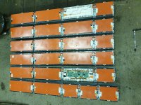
20220108_163001.jpg

Battery will be connected to a 5kva inverter, so each string will not see much more than an average of ~16A flow. I might get another inverter in the long run, but then I will probably get anoter battery as well. In the original 88s3p configuration the battery dlivers more than 200A, so it will be lazy days for the cells.

My problem are the parallel connections. It is not easy (at least not with any of mine equiment) to solder or weld anything to the bus bars. The original bus bars are conected to some spot welded cable lugs, that I can use for attachment for balance wires. Problem is that in my eyes, this looks so sketchy. The cells are perfectly balanced and in good shape, so I guess that not much current will flow thorough the parallel wires, but still.... Does not look right to me. Am I being overly sceptical?
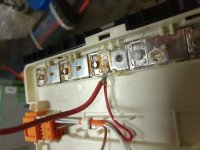
20220108_155726.jpg

I really wanted to use a batrium BMS instead of the usual Aliexpress smart bms'es I've been using before, but then I will either have to build 6 battery strings or use this solution for parallel wires.... Buying batrium cell monitors for 6 strings ends up costing more than what I paid for the battery, so that is not really an option.

Should I just build 6 strings and attach an ANT BMS to each string? I kind of feel like that is my best option now....

What would you do? I am stuck now and cant decide. I would REALLY appreciate pro's and con's or other solutions now, and det on with the build.
 
1) I wouldn't worry about the spot welded tabs. If they worked in the car they will work for you.

2) You can either use six BMSes and six disconnects or connect all the balancing leads (with fuses) to a single BMS. But then you have to monitor the fuses, because if one of them blows something is VERY wrong with the battery.
 
JackFlorey said:
1) I wouldn't worry about the spot welded tabs. If they worked in the car they will work for you.

2) You can either use six BMSes and six disconnects or connect all the balancing leads (with fuses) to a single BMS. But then you have to monitor the fuses, because if one of them blows something is VERY wrong with the battery.

Appreciate the input!
1. What kind of current do you think such a tab could carry? I am not worried about the balance current, but the current through parallel wires if a battery would have some kind of internal fault.

2. I was thinking about using something like this for each parallel group:
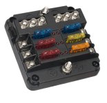
fuse block.jpg
But as you say, the fuses would have to be monitored. What worries me is if one cell group gets a problem big enough that a fuse blows, that problem cell loses monitoring. The string with the problem cell would lose voltage, and the other strings would start feeding it, and I would have a lot of current flowing around undetected, possibly making bad things happen(??)

6 strings with a chinese BMS each (+ an mcb for extra safety and convenience if I were to do any maintenance) would probably be my best shot at this?
 
What kind of current do you think such a tab could carry?
5 amps? Not sure. Most balancers do not need to supply much current; C/200 is usually plenty. Here's a good overview of what sort of balancing power you might need:

http://liionbms.com/php/wp_balance_current.php

I am not worried about the balance current, but the current through parallel wires if a battery would have some kind of internal fault.
Hence the fuses.

The bigger issue I see is that balancing wires are treated notoriously badly - made of thin gauge wire draped haphazardly over the battery. They are lucky if they are taped/glued/cable tied in place; many people skip that. Thus they are vulnerable to damage. Fuses can ameliorate the risk of that sort of failure. Ideally you want the fuses right at the cell itself for maximum protection.

A secondary issue is blowing a fuse due to one node drawing too much current. (i.e. shorted cell) That's not as big a worry because by that time you're going to see other problems with the pack that cause shutdowns.
 
Yes, I agree about the balance leads are often overlooked. I have tried to protect them as good as possible o my small battery packs, but without fuses, it is a pretty big risk anyway. I think i will take the time to use some fuses on the balance wires on this pack. I saw some pack builders on youtube used some really small fuses they soldered to the lugs. Not easy to replace, but it should not ever blow, either....

JackFlorey said:
A secondary issue is blowing a fuse due to one node drawing too much current. (i.e. shorted cell) That's not as big a worry because by that time you're going to see other problems with the pack that cause shutdowns.

But would a centralized BMS always detect that if I were to use fuses for the parallel wires (thats my main worry) before things escalates? If a cell shorted during high SOC and blew a fuse on the parallel wires, the BMS would not see it. The other 5 strings have 4 volts higher pack voltage, and would start to charge the string with the blown cell. The BMS can do nothing to prevent that because they are now connected behind the main contactor/relay....

Hmm... Im starting to think I will just go ahead and order some ANT bms's (one for each string). After all, I have used quite a few earlier and they have always treated me well.
 
What electronics do you plan for the powerwall ? I made a simple system using an APC UPS and cells from a Mitsubishi EV. The APC's let you reprogram the float charge voltage to adapt to non-lead cells. I don't call it a 'powerwall', as I think that term is reserved for fancy systems that know how to redistribute power from-to battery/grid-tie-interter/load.
 
HrKlev said:
But would a centralized BMS always detect that if I were to use fuses for the parallel wires (thats my main worry) before things escalates? If a cell shorted during high SOC and blew a fuse on the parallel wires, the BMS would not see it.
Correct - but - if a single cell in a single string shorts, that cell goes to 0 volts. That could blow the fuse to that cell. But the cells above and below that are going to see drastically different voltages as well, and the system will _likely_ see those as well.

Like I said, for 100% coverage, monitor for blown fuses. But if you don't do that you don't lose _too_ much protection.
 
marka-ee said:
What electronics do you plan for the powerwall ? I made a simple system using an APC UPS and cells from a Mitsubishi EV. The APC's let you reprogram the float charge voltage to adapt to non-lead cells. I don't call it a 'powerwall', as I think that term is reserved for fancy systems that know how to redistribute power from-to battery/grid-tie-interter/load.

I will be hooking up a victron multiplus (possibly 2 in next stage). So I can charge the batteries with the multiplus on nights (in winter) and the solar array (in summer) in combination with the battery will keep the consumption during the day low. The prices differ widely throughout the day around here.

Some days it will be profitable to just charge full at night and sell it during peak hours at day. Will need some fancy programming to do that automatic, though. First of all I need to get battery and solar up and running to cut consumtion during the day and evening.
 
JackFlorey said:
HrKlev said:
But would a centralized BMS always detect that if I were to use fuses for the parallel wires (thats my main worry) before things escalates? If a cell shorted during high SOC and blew a fuse on the parallel wires, the BMS would not see it.
Correct - but - if a single cell in a single string shorts, that cell goes to 0 volts. That could blow the fuse to that cell. But the cells above and below that are going to see drastically different voltages as well, and the system will _likely_ see those as well.

Like I said, for 100% coverage, monitor for blown fuses. But if you don't do that you don't lose _too_ much protection.

Yes, I think I understand and agree. Thanks for your feedback!

So what would you do? 6 chinese bms'es or one centralized batrium?
 
JackFlorey said:
HrKlev said:
So what would you do? 6 chinese bms'es or one centralized batrium?
I think I'd get one of chinese BMSes in and test it - and if it worked well get six of them. Redundancy.

Thanks. I agree, just needed to know Im not crazy for using a handful chinese BMS'es instead of one fancy :lol:

That means I can use a Victron battery monitor to track Amps, SOC, and so on, so one less thing to integrate.

999zip999 said:
What voltage are you looking for ?
My older brother's doctorr in Harstad

It will be a 14s, so ~52V.
Harstad, I think they have a few minutes of sunlight now. We have around 5-6 hours where I live. Solar panles dont make any sense in winter up here, but its nice in the summers :)
 
HrKlev said:
Thanks. I agree, just needed to know Im not crazy for using a handful chinese BMS'es instead of one fancy
You're not crazy - but you have GOT to test them. Some are pretty bad.

I got a cheap BMS a while back. It had 13 separate balance/monitor sections and a control section. The control section pulled all its power off the bottom 2 cells. So it was in a way a "pack unbalancer" as well as a BMS.

Tests I would do:

-undervoltage and overvoltage trip points per cell
-overdischarge current test
-quiescent current draw by the BMS, during storage and discharge
 
JackFlorey said:
You're not crazy - but you have GOT to test them. Some are pretty bad.

I got a cheap BMS a while back. It had 13 separate balance/monitor sections and a control section. The control section pulled all its power off the bottom 2 cells. So it was in a way a "pack unbalancer" as well as a BMS.

Tests I would do:

-undervoltage and overvoltage trip points per cell
-overdischarge current test
-quiescent current draw by the BMS, during storage and discharge

Yeah, I actually got 5 of the ANT bms's running in different vehicles around here, 4 of the "old" types and one of the "new" 21 version. All from same seller, ICgogo or something. Oldest one are 3 years now. All of them are keeping the packs perfectly balanced (even though the 2 that is running with old LEV40 packs dont need to do much balancing), and shuts down on temp, current and volts, pack level or cell level. So I am very happy with them, but I have no idea if they will last 10-15 years as I hope my powerwall will. I will find out.

The price for 80 vs 300 was so small that I went ahead and ordered 300 amp versions. So at least they will not be stressed. Should not see much more than 20 Amp draw each in normal conditions.
 
Back
Top