Modular Battery suitcase

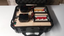
Can assure you NOT trolling, but rather calling you out as to why you didn't test and balance the cells (at least within 100mV) before making up your 14 p-groups of 10p. Likewise it would be of some importance to know the brand of cells you are using and their condition having been in storage "collecting dust" ... especially with such a wide range of p-group variances from 3.584V (8p) to 4.195V (14p).

A DIY build (no matter how good) is no better than the condition of its cells. My post(s) should be viewed as constructive critique and NOT trollling. Hoping you do realize that that is the case with your DIY battery case. Your simplier build that proves to be just as good or possibly even better requiring less expensive equipment and not as labor intensive as a DIY spot-welded build.
Dui said:
Trying to get all cells within 50mV of each other, then hopefully the BMS should be able to take them within 0.001V
Don't be disappinted (as none of us will be disappointed) if your 'smart' BMS only balances p-groups within 25mV of each other.
Please do let us know how long it takes your BMS to balance all fourteen 10p groups from 50mV to within 25mV of each other.
 
It is fine to ask questions but your hunger for more and more information is expressed as entitlement, comes off as belittling and aggressively confrontational.

Be grateful they are going to so much trouble already to share their obviously superior level of skills and knowledge, and just back off with the challenges and unending demands.
 
john61ct said:
It is fine to ask questions but your hunger for more and more information is expressed as entitlement, comes off as belittling and aggressively confrontational.

Be grateful they are going to so much trouble already to share their obviously superior level of skills and knowledge, and just back off with the challenges and unending demands.
What would we/i do without your input ... thanks for your constructive critique ... even if a tad over-the-top ... :)
 
FWIW, I do recommend, to all posters helping anyone, to use a method in presenting troubleshooting options that only presents the options, and doesn't "demand" anything of them.

Some people find it confrontational otherwise, and arguments then ensue, helping no one. ;)


The same applies to questions about a project, especially one someone is simply documenting to share with others.
 
I also let the bms equalize my 21S5P (100Ah) scooter battery. It took nearly a week, but was much less work for me than clamping 105 cells to an RC-charger and wait up to an hour for each cell until they are at the same voltage level. I checked the cell with the lowest and the highest voltage level with my RC-charger they where within 1% of capacity tolerance. So everything was fine for me.

My DIY RC-charging case with integrated 6S2P 60Ah Li-NMC was balanced after assembling with a standard RC-charger, as I did not even think of integrating a bms. There was no space left inside the case under the chargers and next to the batteries. The case had to be the smallest to fit my existing batteries. Balancing is only done when the battery is charged with the RC-charger. Undervoltage protection is set in the ISDT Q8 chargers.

There are a lot of different ways how people do their work.
If they are not trying to kill themselfs or others with or during their work, everything is ok for me. :wink:

Dui go on with your work and let us see your results. They are always inspiring.:thumb:
 

Attachments

  • 20220304_171732.jpg
    20220304_171732.jpg
    2.2 MB · Views: 232
  • 20220215_215531.jpg
    20220215_215531.jpg
    3.6 MB · Views: 232
dominik h said:
I also let the bms equalize my 21S5P (100Ah) scooter battery. It took nearly a week, but was much less work for me than clamping 105 cells to an RC-charger and wait up to an hour for each cell until they are at the same voltage level. I checked the cell with the lowest and the highest voltage level with my RC-charger they where within 1% of capacity tolerance. So everything was fine for me.

Your RC charging case looks awesome, well done!

Yeah, that was the idea: it is faster/easier to charge 14 modules than it is to charge 140 cells.
What I did was to pick cells that had "close enough" voltages, put them in parallel in the modules. This way they auto equalize (their voltage needs to be close otherwise they'd heat and potentially get damaged because there is basically nothing limiting their charge current).

Next, the plan was to charge each module individually with the charger until they reached 50mV, but this turns out to be a hassle. So right now I think I will get them within 0.1, maybe 0.2V and parallel the modules together, using some thin wire to limit the current. This way they should all equalize a bit faster.
 
If you can get groups to within 0.1V before joining then no worries with fat connections.

Limiting flow by using high resistance thin wire can be dangerous.

Consider getting everything above a certain voltage, then using a cheap resistance based device designed for the purpose to discharge to a common voltage.

Example product for 1S https://www.tinywhoop.com/products/tiny-whoop-1s-discharger-pw-jst2-0-battery

DIY, any voltage S-count

https://www.rcgroups.com/forums/showthread.php?1255751-Poor-Man%C2%92s-5-Regenerative-Discharger

 
I would paralell them with wires 1,5mm² 10-20cm length (awg 15 to awg 16 about 3-6") this should limit the current to values around 20A and should not burn the wires when the cells are within 0,1V.
 
dominik h said:
I would paralell them with wires 1,5mm² 10-20cm length (awg 15 to awg 16 about 3-6") this should limit the current to values around 20A and should not burn the wires when the cells are within 0,1V.

Yeah that is exactly what I meant actually, I do realize now that "thin wire" was a poor choice of words, by that I meant I won't use the massive copper bus bars to parallel the cells. :wink:
My plan was to do almost exactly what you said, but using a little bit longer wires to get a little bit more voltage drop. I have the infrared camera to monitor the wire temperature. I don't expect it to get very hot since the cells will be pretty close to each other already. Right now they are all within 0.130V of each other, I'm almost there!

john61ct said:
Example product for 1S https://www.tinywhoop.com/products/tiny-whoop-1s-discharger-pw-jst2-0-battery

DIY, any voltage S-count

https://www.rcgroups.com/forums/showthread.php?1255751-Poor-Man%C2%92s-5-Regenerative-Discharger

Nice, thanks!
I DIYed something similar to discharge the highest cells, just using a few wires and a filament bulb. It's is a bit slow but it works fine.
 
Very nice build. The 1s module look awesome / mint. Dui ni shuo de dui

I like to get a 3d-printer to do some kind of similar modules. I do however need 75ah total capacity and 2 modules in parallel is almost not enough.

I have 5s27p 65ah modules at the moment and have made repairs to them from time to time with unknown reason for the error occurence.

The reason is one can build the module in your own geometry and design and also it can be faster to swap out a dead module if that would happen

As in all project they take time. I hope to buy a 3d-printer as a start
 
Very nice build. The 1s module look awesome / mint. Dui ni shuo de dui

[...]

As in all project they take time. I hope to buy a 3d-printer as a start
That's great, let me know if you need any help with your project!
 
Thank you.

I did get a 3d printer a flashforge one and I can do unto 15x15x15cm in size and it is just too small to make any longer module. However it got me thinking that a few rows ain't a bad thing either.

7p is maximum in a row and 6 by 6 in a square printing a module giving an amout of maximum 36 cells. I need a minimum of about 22p of 3,5ah 18650 or 77ah to get any more benefit than I have right now. 36p will get too big(126ah) I think and 18p will be the bare minimum I'd like to have. A change to 21700 would be a possibility but a more expensive one but would then give almost 90ah which is great as a 2s18p module. (18s, making it 9 pieces to connect rather than 18 pieces)

Then I have a question about the material and the infill as more grams equal more efficient heatpipe properties to remove heat from the cells outward. Building it in PLA is what I've got and if that ain't up for the work then I might rethink my plans to use 3d printer forms.

Also rather than using a lot of material I try to minimize this. A bottom and a top cellholder could work as a frame for the cells and also make it very sturdy making the modules easy to assemble and connect with other ones.
 
How will more used modules effect your build? Lets say you use the case as 12v and then decide to add more and get 72v. Wont the modules used for 12v effect the performance of the now 72v case? What do you think about that?

Also what material are you printing with?
 
Back
Top