Aluminium torque plates: your choice. (Corrected)

Buk___

10 kW
Joined
Jul 28, 2017
Messages
750
Update: Math corrected. I'd made several mistakes, but the upshot is that once corrected, it makes the point even more strongly.
(Why did I my errors earlier? My excuse it that it is the adversarial nature of this place, and certain member's predilection for using pedantry to score cheap 'points' rather than engage, has made my first reaction to criticism, hostility. If those that noticed the errors, posted clear descriptions of them rather than veiled allusions to them, those criticisms would be accepted. If they posted corrections, that would be even better. That, and it's been 20 years since I used this stuff on a regular basis, so its rusty. )

Aluminium strain hardens. As it deforms and rebounds within its elastic limits during use, the microstructure of the metal changes and it becomes more brittle over time.

Assume a fairly ordinary DD hub producing say 20Nm torque acting at the 80mm air gap radius means 250N of force. With a M14 axle with 10mm across the flats, the edges of the flats are acting on the thickness of the torque plate(s) at a distance of 7.21mm; magnifying that force to to 2774 N.

If the edge of the axle flat has a radius (many don't) of 0.25mm, and the plate is 10mm (3/8th" thick), with 2774N of force acting on a 0.01m x 0.00025m area, you have 1109.6 MPa of shear force. And that is steady state.

The shock loading from accelerating, braking and dropping off curbs can 5-20 times higher.

With Al 6061-T6 having a yield strength of 241 MPa when new, 10mm thick torque plates are barely adequate at best,
if the bearing surface is a 10mm x 0.25mm flat area.

Now consider that a M14 course thread with a 2mm pitch would have at most 6 thread points of 2mm/8 width in contact.
That reduces the bearing surface to 6 x 0.00025m x 0.0005mm, and the shear force has climbed to 3,698 MPa steady state.

Yes, as the threads dig in the bearing surface area will increase, but by then, the 5 or 6 point contacts have created
a line of stress risers across the thickness face of the TP.

From the side, there will be no visible sign of a problem. Any small signs of deformation will be covered by the nut.

Internally, that line of stress points will have set up the start of slip fractures in the grain structure, and every time you brake, accelerate, hit minor road imperfections, the lattice dislocations along the slip plane ahead of any plastic deformation grows as the strain-hardened embrittlement spreads.

Eventually, the sharp edge of the axle flat, armed with its serrated teeth, will slice through the embrittled plate like an apple corer.
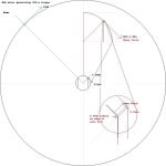
AxleFlatShearStress.jpg
 
amberwolf said:
This means the same thing applies to all the aluminum dropouts themselves (front or rear).

For normal axles without flats, this particular problem doesn't occur.

For hub motors, torque arms/plates are recommended for all but the most minimal powered setups, regardless of the dropout material.

Even though the yield strength of plain old mild steel is little higher than 6061 at 247, it doesn't stress harden and retains its ductility, so if it is highly loaded it will not snap, but rather, shear slowly over time.

316 stainless steel with a yield strength of 500-700 MPa should be good for all but the most hot-rodded hubs.

Most of the problem can be mitigated by radiusing the thread points back from the flat edge so that a full width bearing surface contacts the the dropout/TP face.
 
To mitigate localized affects, could the slot in an aluminum torque-arm be widened and then lined with two steel flat-bars?

Or would the aluminum still form cracks due to the stresses?

file.php
 
spinningmagnets said:
To mitigate localized affects, could the slot in an aluminum torque-arm be widened and then lined with two steel flat-bars?

Or would the aluminum still form cracks due to the stresses?
Sure. The steel would (assuming enough thickness) prevent thread points digging into the Al. (There's the problem of attaching the steel to the Al and it would need to be pretty well finished and fitted to prevent surface anomalies/corners on the steel creating their own stress risers, but some careful work with a fine file would take care of that.)

Even a thin layer would mitigate a lot of the problem. A piece of (0.381mm) tin can steel wrapped around a 0.25mm radius increases the contact area by 2 1/2 times, thus reduces the shear stress by the same factor.

spinningmagnets said:

That said, I'm dubious about those extension pieces. I assume the long slot is intended to allow for chain length adjustment/stretch take up; but depending how far back the axle sits in the slot, the combination of torque moment forcing the jaws apart, and the leverage, that bottom jaw section looks to be the weak point.
 
Good info, and I don't dispute your overall point. Couple critiques of the argument, though.

First, 20 Nm at the air gap is... 20 Nm at the axle. Force is multiplied as the radius decreases, not torque. Hopefully Nm vs. N doesn't join Wh vs W in the ES confusion hall of fame.

Second, the maximum force occurs at the edge of the flat, but it isn't all concentrated there - the force is distributed across the face of the flat. If it doesn't start out that way, it happens as the edge deforms the TA surface elastically and the flat surfaces are pressed together as a result.
 
cycborg said:
Good info, and I don't dispute your overall point. Couple critiques of the argument, though.

First, 20 Nm at the air gap is... 20 Nm at the axle. Force is multiplied as the radius decreases, not torque. Hopefully Nm vs. N doesn't join Wh vs W in the ES confusion hall of fame.

Second, the maximum force occurs at the edge of the flat, but it isn't all concentrated there - the force is distributed across the face of the flat. If it doesn't start out that way, it happens as the edge deforms the TA surface elastically and the flat surfaces are pressed together as a result.

If I understand the original post correctly, that analysis assumes all of the torque is transmitted via the flats of the axles and does not account at all for any forces transmitted to the faces of the dropouts via the clamping forces of the axle nuts. In other words, it assumes that that axle is free to rotate with only the dropouts and torque arm there to restrain it.

Also, it is unclear whether your calculations refer to the use of a single torque arm or two.
 
spinningmagnets said:
My apologies for not including all the info. This style is intended as a "pinching" torque arm, and the clamping device is mild steel:

file.php

I love seeing the ingenius designs of T.A.'s
In that picture, I see its using cable tie'r togethers. Its good.
Maybe use those lock bolts on the axle so they bite into the T.A. - Sorry the brand name escape me off hand. A sleeker idea would be to tap some threads, but thinking about it now that would be weak.
 
cycborg said:
... the force is distributed across the face of the flat.

If your dropout/TP has any clearance -- and all non-pinch-plate type do to some more or less degree -- then the edges of the two flats diametrically opposite each other (red circles) act as fulcrums pushing the crown flats of the threads into opposing faces.

The image below approximates 0.25mm of clearance (half each side):TAslop.jpg

Of course, you could try and centre the flats between the faces, or press them over to one side or other, and hope that the tension/friction from tightening the nut will prevent it from moving...good luck with that.

Pinch plates are good, but it is still those diametrically opposed sharp edges that will act in shear, not the flat faces. And in Al, those shear forces will embrittle over time.
 
We had experiences with the Borg Warp frame and the inbuilt slotted axle dropouts. They were designed horizontally so that chain tension could be adjusted by seating the hubmotor back in the slots, like some motorcycles. The frame is chrome moly steel. I'd have to measure the width of the dropouts, but they are neither narrow nor ridiculously wide, only about 1/4" IIRC.

What was discovered early on is that when the hubmotor was set back in the slots to tension the chain, the slot in the dropouts was not able to resist the axle rotation, and even modest hubmotors (especially those with 12mm axles flatted to 10mm) would spread open the dropout and spin. This is a different type of failure, but is another one to analyze for. If Chrome Moly Steel had a problem with stretching in this way I would be concerned about other materials as well.

I was advised by the manufacturer of the Warp Frame that I should never allow the Cromotor to sit back of the most forward location in the dropout, and fully forward it would not need torque arms or plates. So I lost the ability to tension the chain that way. But the Cromotor, even with far greater torque than most hubmotors, never has had any problems with the slot, and it has no torque arms or plates (or pinching bolts/etc), beyond those two 10mm slotted dropouts and the 16mm axle flatted to 10mm. NordLock washers have been employed there and they work well to keep the nuts tight.

I had to use a chain tensioner to solve the chain issue, but avoiding the torque arms or plates makes removing and reinstalling the hubmotor wheel a bit less fiddly.

If the torque plate / dropout is a pinching type this failure is most likely avoided. It stems from the additional leverage from moving the axle away from the end of the slot, in effect giving it more leverage to apply in straining the material.
 
Alan B said:
What was discovered early on is that when the hubmotor was set back in the slots to tension the chain, the slot in the dropouts was not able to resist the axle rotation, and even modest hubmotors (especially those with 12mm axles flatted to 10mm) would spread open the dropout and spin.

Indeed. Leverage is a bitch and with the torque turning the flat edges into fulcrums, the radii make very effective wedges.

With a 12mm diameter/10mm flats, you only need to stretch and/or wear the material on each side by 1mm and you have a plain bearing with serrated bearing surfaces; otherwise known as a router! Guaranteed to spoil your day.
 
wturber said:
Also, it is unclear whether your calculations refer to the use of a single torque arm or two.

1 x 10mm thick or 2 x 5mm. Adjust proportionally,

With respect to the friction of the nuts relieving the stresses.

When you do the nut up, as you turn the nut from finger tight (just contacting) to the torque need to achieve the required tension, you are overcoming the friction between nut and TA with your hand at the end of a (say) 200mm spanner.

As your rear tyre drops down the curb, your entire bodyweight is acting at the periphery of your wheel, say 330mm radius.

When you are rolling along the road at 20mph and you hit the brakes, you and your bikes mass times your forward velocity are acting at that distance.
 
Buk___ said:
amberwolf said:
This means the same thing applies to all the aluminum dropouts themselves (front or rear).

For normal axles without flats, this particular problem doesn't occur.
Sure, but since the thread was about using hubmotors with aluminum I guess I assumed :oops: that anyone reading would take my statement to apply specifically to those. ;)

I should've been more explicit.

For hub motors, torque arms/plates are recommended for all but the most minimal powered setups, regardless of the dropout material.
Yes, and I suppose what I was trying to point out to readers of your analysis was that it shows *why*. :)
 
amberwolf said:
Buk___ said:
amberwolf said:
This means the same thing applies to all the aluminum dropouts themselves (front or rear).

For normal axles without flats, this particular problem doesn't occur.
Sure, but since the thread was about using hubmotors with aluminum I guess I assumed :oops: that anyone reading would take my statement to apply specifically to those. ;)

I should've been more explicit.

For hub motors, torque arms/plates are recommended for all but the most minimal powered setups, regardless of the dropout material.
Yes, and I suppose what I was trying to point out to readers of your analysis was that it shows *why*. :)

Sorry, my misunderstanding. I wasn't quite sure what point you were making, and didn't want to leave you unresponded, so I tried to cover it from every angle :)
 
Just a reference and top'n'tail quotes as teasers.

Long ago, engineers discovered that if you repeatedly applied and then removed a nominal load to and from a metal part (known as a "cyclic load"), the part would break after a certain number of load-unload cycles, even when the maximum cyclic stress level applied was much lower than the UTS, and in fact, much lower than the Yield Stress (UTS and YS are explained in Stress and Strain). These relationships were first published by A. Z. Wöhler in 1858.

It is important to realize that fatigue cycles are accumulative. Suppose a part which has been in service is removed and tested for cracks by a certified aircraft inspection station, a place where it is more likely that the subtleties of Magnaflux inspection are well-understood. Suppose the part passes the inspection, (i.e., no cracks are found) and the owner of the shaft puts it on the "good used parts" shelf.

Later, someone comes along looking for a bargain on such a part, and purchases this "inspected" part. The fact that the part has passed the inspection only proves that there are no detectable cracks RIGHT NOW. It gives no indication at all as to how many cycles remain until a crack forms. A part which has just passed a Magnaflux inspection could crack in the next 100 cycles of operation and fail in the next 10000 cycles (which at 2000 RPM, isn't very long!).
 
I don't agree with some of what has been claimed here (who's surprised). Be very careful about making claims. As was pointed out, torque is not multiplying whereas force in some cases is. These errors will contribute to mistrust of the real issues and the entire discussion. Be clear and precise. There are some potential issues and some non-issues that are being mixed here.

For example, steel dropouts are used in large numbers of commercial hubmotored ebikes without torque arms or problems at power levels of 250, 500 and even 750 watts, often with peaks to twice that. At low speeds the torque may double or triple due to controller motor current multiplication. Aluminum alloy dropouts are used in millions of standard bicycles with threaded axles without problems, while applying brakes and dropping off curbs every day.

Dropping off a curb doesn't cause significant torque on the axle. Axle to dropout force is not all or even mostly torque. Standard axle forces are significantly lower than torque induced forces with large lever arm ratios on flatted axles. Threaded axles in alloy forks work fine.

Braking with rim or disc brakes doesn't cause net axle torque to any significant degree like hubmotor acceleration or regen does.

Aluminum and steel behave significantly differently, especially in terms of cumulative stress cycling. Steels do not tend to fail suddenly the way aluminum sometimes does.

Aluminum aircraft undergo millions of flexing and vibration cycles without failure when designed properly. Flexing doesn't automatically guarantee failure in aluminum as is being implied here.

Torque arms actually increase other reaction forces on the alloy dropouts when torque is present. Attention should be paid to the directions of these reaction forces when designing and installing torque arms. For example the locations of the torque arm pivots controls the resulting force vectors on the dropout during torque events, and you don't want that force in the wrong direction, where it may push the axle out of the dropout vs pushing into it. With regen these forces alternate directions. At some point keeping the axle nut tight becomes very important (and in many cases difficult).
 
Alan B said:
Be very careful about making claims.
I make no claims. I did some math.

Alan B said:
As was pointed out, torque is not multiplying whereas force in some cases is.

[strike]That pedent's comment got the response it deserved. The math is correct. The equation for leverage is simple.[/strike] F1 * D1 = F2 * D2.

Alan B said:
For example, steel dropouts are used in large numbers of commercial hubmotored ebikes without torque arms or problems at power levels of 250, 500 and even 750 watts, often with peaks to twice that. At low speeds the torque may double or triple due to controller motor current multiplication.

Steel doesn't embrittle.

Alan B said:
Aluminum alloy dropouts are used in millions of standard bicycles with threaded axles without problems, while applying brakes and dropping off curbs every day.
Standard bicycle axles don't have flats.

If the axle rotates, it just rotates in place, with nothing (beyond wheel nut tension/friction) to stop it, and no harm if it does.

Alan B said:
Dropping off a curb doesn't cause significant torque on the axle. Axle to dropout force is not all or even mostly torque. Standard axle forces are significantly lower than torque induced forces with large lever arm ratios on flatted axles.

Unless you are stationary, any force acting on the tyre has a torque component.

If you come off the curb under power, for the split second the tyre is not in contact the wheel goes faster than the bike, when it contacts the road again, the imbalance has to be corrected. The bike jerks forward a little; and the wheel slows down.

When the rim slows, the rotor slows, when the rotor slows the bemf drops, the phase voltage rises and the torque builds. That torque acts on the stator, and that's attached to the axle.

Alan B said:
Threaded axles in alloy forks work fine.

Once again. Its not the threads, its the threads cut through by flats, producing teeth that are then fulcrumed into flat surfaces.

Alan B said:
Braking with rim or disc brakes doesn't cause net axle torque to any significant degree like hubmotor acceleration or regen does.
With a direct drive hub, unless the wheel is locked and the tyre skidding, the motor is acting as a generator and that causes torque in the opposite direction to drive torque; which acts on the stator and the attached axle.

A geared hub with sprag clutch not so much.

Alan B said:
Aluminum and steel behave significantly differently, especially in terms of cumulative stress cycling. Steels do not tend to fail suddenly the way aluminum sometimes does.

Did I suggest otherwise?

(But, if the steel is hardened, it can fail under cyclic stressing:
In general, steel alloys which are subjected to a cyclic stress level below the EL (properly adjusted for the specifics of the application) will not fail in fatigue. That property is commonly known as "infinite life". Most steel alloys exhibit the infinite life property, but it is interesting to note that most aluminum alloys as well as steels which have been case-hardened by carburizing, do not exhibit an infinite-life cyclic stress level .

Alan B said:
Aluminum aircraft undergo millions of flexing and vibration cycles without failure when designed properly. Flexing doesn't automatically guarantee failure in aluminum as is being implied here.

Sorry, but it does.

Aircraft use aluminium because they have to -- it's the only economically viable option to satisfy their strength to weight ratio requirements (prior to carbon composites) -- but it comes at a high cost. That of an expensive extensive, rigorous, and mandated maintenance schedules that involve stripping the aircraft down to its shell, and then stripping away large parts of that shell (and the bones beneath) and replacing them on a regular basis.

See this for (much) more details on that; and know what you see there, is a précis of a précis. All aluminium work hardens and is subject to fatigue fracturing after sufficient cycles. And it happens much earlier than most people think.

I quote this again; this time with highlighting:
Long ago, engineers discovered that if you repeatedly applied and then removed a nominal load to and from a metal part (known as a "cyclic load"), the part would break after a certain number of load-unload cycles, even when the maximum cyclic stress level applied was much lower than the UTS, and in fact, much lower than the Yield Stress These relationships were first published by A. Z. Wöhler in 1858.

You're not arguing with me, but with a 160 year old engineering fact of life.

Like Dan and LiPos, I harp on about this because I've seen the results with my own eyes. But in the end, I said it in my original title: "your choice"

For third party observers: Don't take my word for it -- but don't take guesswork either -- look it up, and then make your own informed decision.

Alan B said:
... With regen these forces alternate directions.

Unless there is a clutch to prevent the motor generating when slowing down with no phase current, then the torque on the stator/axle alternates regardless of whether you are using regen.

And it is exactly those types of cyclic forces that cause cyclic stress (work hardening) and associated failures.
 
cycborg said:
First, 20 Nm at the air gap is... 20 Nm at the axle. Force is multiplied as the radius decreases, not torque. Hopefully Nm vs. N doesn't join Wh vs W in the ES confusion hall of fame.

I apologise for treating this correct critique dismissively.

Recent snipping and pedantic point scoring by another member has made me oversensitive to critique that on first blanche appeared to be akin to a European correcting an American's use of pounds-foot rather than the more proper pounds-force-foot.

I've updated the root post, with (hopefully) correct math, with the upshot that it is an even stronger argument against Al for this use.
 
My Strong GTS bike that was sold by Canadian Tire is a steel frame with flat steel drop outs that acted like their own T.A.'s but yet it still had a wonky U shaped thing as its dropout. The U was to go around the axle nut.
 
Buk___ said:
wturber said:
Also, it is unclear whether your calculations refer to the use of a single torque arm or two.

1 x 10mm thick or 2 x 5mm. Adjust proportionally,

Thanks.

Buk___ said:
With respect to the friction of the nuts relieving the stresses.

When you do the nut up, as you turn the nut from finger tight (just contacting) to the torque need to achieve the required tension, you are overcoming the friction between nut and TA with your hand at the end of a (say) 200mm spanner.

I probably did not make my point clearly. Many years ago (long before I ever showed up here) Justin did some destructive testing on dropouts to investigate the effectiveness dropouts resisting the motor axle flat torque. He tested without torque arms but with the axle nuts tightened at different torques, with torque arms tightened down by nuts at different torques, and with torque arms that not tightened down at all with axle nuts. The upshot was that if the axle nut is tightened to about 40-60 ft/lbs of torque the amount of torque it takes for the axle to destructively deform the dropout is significantly increased. Tightening beyond that had only a small effect. In short, axle nut torque amounts have a significant effect on the forces that the axle flats will transfer to the sides of the dropout. Your calculations do appear to consider this. If I understood them correctly they assumed a torque arm that is not tightened down at all. It might be worth some attempt to account for that in your analysis if the goal is to predict/estimate real world effects.
 
wturber said:
Your calculations do appear to consider this. If I understood them correctly they assumed a torque arm that is not tightened down at all. It might be worth some attempt to account for that in your analysis if the goal is to predict/estimate real world effects.

No. I understood you, but the problem with accounting for it, is the counter force commonly known as stiction.

If you can make the nut overcome friction when torquing the nut with a shortish wrench, then the forces generated by riding can also.

And when they do -- as anyone who's undone an overtightened nut can attest -- torque doesn't overcome friction smoothly and progressively , but rather all at once in jerks. It's very hard to model discrete and non-deterministic functions like that.

Once the friction is overcome, it is like it isn't there until it the force applied eases -- the spanner moves quickly so the pressure you apply drops rapidly, the friction grips again, and usually the spanner or socket slips off and you skin your knuckles.

For those moments where the friction is overcome, the axle rotates a little taking up any play and the fulcrum effect kicks in, so the shear forces acting on the dropout /TP are a shock loading, probably well in excess of the steady state torque the motor can produce.

In the real world, you don't calculate those forces, you apply a strain gauge and measure them, and then design your part to take the maximum load experienced plus some safety factor.

My attempt here was to show how steady state forces are multiplied by the leverage of the radius where the torque is sourced, and the radius where it is acting. For torque generated at the gap in an 80mm stator, the force acting at the edge of the flat is 11 times higher.

In physics, torque is defined as the rate of change of angular momentum.

Induction is defined as the rate of change of the magnetic flux enclosed by the circuit.

If you drop off a curb under throttle, the motor speeds up at the no-load rate (fast), when the tyre reconnects, the motor slows down even faster. Those both represent high rates of change in angular momentum. That means high rates of change in magnetic flux and high levels of induction acting 'tween rotor and stator; and that transmits back to the axle.

Those pulse loading are complex to calculate, but it isn't the ultimate force that is of concern with Al experiencing shock loads, but rather their cumulative effect over time. Unless Jason ran his tests to destruction; and then repeated them with enough 'identical' parts to arrive at a statistical average; then as with the magnetically crack-tested aircraft part above, when the test concluded, it only told you that that part hadn't failed. Yet!

Not, that it wouldn't fail, first thing tomorrow, or next week.

The only way I know of to check for shear slippage -- where the planes of atoms within the metal's crystal structure slide past each other, by one or two atoms at a time:
ElastiPlast%202-1.png
Dislocations+in+the+crystal+lattice.jpg


-- is to section the metal and inspect it with x-ray crystal tomography. At the late stages just before failure, it can be observed under an optical microscope in sectioned samples that have been prepared by etching, but at that point, it's too late. Even if the test wasn't destructive.

Cracks in Al that has embrittled through cyclic loading, tend to propagate much more quickly than in new, tempered Al. And like that sticking nut above, when they go, it tends to be all at once rather than progressively.

My math was only meant to demonstrate the scale of forces involved; and magnification factors that are at play; not as a design guide. It'd need much more accurate examination and instrumenting of the forces and leverages involved to come up with that.

The take away from the first post was meant to be:

  • Al is the wrong material for this purpose.

    It embrittles with cyclic loading and would require such a wide face to build in a safety margin, that you'd run out of axle.
    (And weigh more than the required thickness of even ordinary mild steel, which doesn't age,)

    There is no benefit to using Al for this.
    .
  • Even a small radius on sharp edges can significantly reduce the stresses

    A sharp knife cuts even tough wood and leather fibers easily. Sharp edge, point loading. Put a 0.25 mm radius on it and you'll be lucky to mark the surface.

    The reduction isn't of the order of 50%, but more like 9x%.

    Assuming the axle is harder than the TP (a good thing), then if the point was 1 micron wide, then radiusing to 0.25mm increases the area the force acts on by 250 times. That's a 96% reduction in the shear forces. And 0.5mm gives a 98% reduction.

    I can't state that the edge will be 1 micron wide. Below a certain size, the first contact will dull the edge -- in the way knife edges 'roll over' -- but there comes a point where the width of the steel axle edge is strong enough to sustain itself at the atomic forces level, and that's when it starts transmitting shear force to the Al.

I don't blame people for questioning the statements. It does get quite tiresome when they don't bother to read and understand the description.

My bad math doesn't help, but it is actually immaterial, as pretty much everyone intuitively understands leverage -- ask anyone to open a paint can and they'll reach for a screwdriver -- and that's all you really need to know about the forces involved.
 
Back
Top