Any controllers capable of maintaining smooth RPM decay rate under suddenly varying load?

bikerpete

100 W
Joined
Jan 27, 2020
Messages
227
I've been looking around for a controller that might be able to maintain a fixed RPM decay rate even as load varies.
ie. from high RPM the throttle is closed, the motor should maintain a more or less constant RPM decay rate even if the load is totally removed then suddenly increased. Obviously within the limits of the motor & controller - if the load is too high the RPM will of course drop suddenly.

Effectively the controller needs to take control of the throttle input to respond to excessive decrease in RPM.

In a totally ideal world it would be possible to:
Adjust the maximum current that the controller will deliver to maintain RPM.
Adjust the current ramping response (so the response can be more or less instantaneous to changes in load.)
Adjust a time threshold for the response to decay (ie in response to an instant large load increase the current would spike to maintain RPM, but then would decay over the time constant.
Set up separate attack (rising RPM) and decay profiles.

My goal is to somewhat electrically simulate the effect of a flywheel.

I'd hoped that some of the scripting ability in Silixcon controllers might be able to do at least some of this, but after spending time reading their resources I'm not so sure it could. Still researching.

My guess is that this is likely so far out of mainstream needs that it's not going to be available without some moderately serious software development by a controller manufacturer.

Oh, and if that same controller had the ability to set an 'idle' rpm that would be gold. And if that idle rpm could have it's current limit manipulated (effectively to set a 'stalling load' theshold) that would be ... platinum?
 
ebikes.ca's phaserunner is capable of virtual freewheeling, but i'm not sure if that's exactly what you're looking for.

BTW why do you need this?
 
ebikes.ca's phaserunner is capable of virtual freewheeling, but i'm not sure if that's exactly what you're looking for.

BTW why do you need this?
Thanks, but I don't think virtual freewheel is really anything much like I'm after. That applies just enough power to the motor to overcome it's drag. I want to actively control RPM.

I would like to experiment with electronic flywheel effect on moto trials bikes. To the best of my knowledge no one has done this.

When you cut throttle with a heavy flywheel everything decelerates gradually. If the load is released it continues to decelerate, it never accelerates when load is removed. If a sudden load is applied at the wheel then the flywheel intrinsically supplies instantaneous big-time torque and loses energy rapidly (and obviously slows quickly).
Picture a moto - rev it up, drop the clutch & close the throttle and launch airborne. Then the back wheel impacts on a vertical rock face and climbs up it. At the top there should be very little energy left in the system so it's easy to come to a complete stop and position the bike.
A physical flywheel does this really well, accelerates the back wheel crazy fast to create lift, then as it unloads it simply freewheels without spinning up. When it hits the rock there is instantly a huge surge of torque out of the flywheel, right when the tyre is slammed hard against the face, accelerating the bike & rider vertically up the face. The energy is very rapidly consumed, so when you get to the top there's barely any energy left and you once again adjust on clutch and throttle.

I'm trying to emulate that to some extent with a fairly simple electronic analogy.
  • RPM is set to decrease at fixed rate
  • If RPM decreases faster than the set rate, increase current to motor (probably some sort of PID to relate Delta RPM to Current).
  • Ramping the current increase might help make things more or less "brutal".
  • Current limit should emulate the inertia of the flywheel to some extent.
  • By adding a time constant the current would fall away over time, emulating the flywheel losing energy. Pretty rough approximation, but the best option without doing a lot of maths to calculate consumed power and subtract that from a "virtual flywheel energy" calculation.
I don't hold out much hope of finding such an animal, nor do I expect it to provide anywhere near the superb response of a dumb flywheel. But maybe it could add a degree of tuneability to a physical flywheel and reduce the overall mass required, or make a flywheel-less bike much more rideable.
 
Last edited:
the superb response of a dumb flywheel
Pardon me asking - have you actually done this with a 'dumb flywheel'. Not maybe, or 'I think it should work' - I mean, have you done this?
 
Pardon me asking - have you actually done this with a 'dumb flywheel'. Not maybe, or 'I think it should work' - I mean, have you done this?
Good question - yes. Many hundreds of hours.
I've also added a 20mm disc of steel the full outside diameter of a QS138 motor to give it more inertia, with excellent results.
I'd be inclined to say that bike has the best response off clutch of any e-trials I know of, bar none.
Edit: I know a bloke who's made a copper/tungsten (denser than lead) flywheel for his Electric Motion - that should prove fairly effective despite the anorexic diameter.

Realistically I suspect my only option is going to be to fit a microprocessor between throttle and controller. That could read motor RPM & throttle position & then output throttle signal as required.
But that's a very poor cousin because the controllers' throttle ramp rate will still be in play & is probably going to be much too slow.

So the search continues for a controller with a lot of programmable flexibility.
 
Last edited:
My guess is that this is likely so far out of mainstream needs that it's not going to be available without some moderately serious software development by a controller manufacturer.
You can easily program this with any of the various open source projects. Even with a very cheap Kunteng. ;)
 
Yeah it sound like a pretty specific requirement that will require custom programing, probably best to pick the controller firmware that is easiest to program and go from there. I've looked at the VESC lisp scripting a bit and it seems pretty straightforward and you can get some help if you have any issues on the VESC discord scripting channel.
 
A physical flywheel responds according to the interaction of it's inherent characteristics with it's environment - it has mass and angular momentum in a universe with characteristics that leads to certain behaviour - which you find convenient.

Your (any) electric motor/bicycle has it's own relationships and thus it's own response to events (your scenario of climbing, for instance).

The flywheel does not "know" of the events - it responds as it responds. The motor/bicycle the same - as formed now, it has it's inherent response to your scenario - but you are not satisfied with it's current response.

You want the motor/bicycle to respond as the flywheel does.

You are approaching this not by modifying the motor/bicycle to have the inherent characteristics of the flywheel (e.g. adding a flywheel) - rather you want to mimic this actively with electronic motor controls.

How does your motor "know" it's speed has been cut by the change (slowed), and by how much? What time increment is sufficiently small that the active system can respond in such a way as to maintain the response curve you want?

Have you done these calculations yet? This tells you how quick your sensors and electronics must be. (Aside to the peanut gallery - don't tell us 'electronics are fast'. We know this and it's useless to write.)

Have you instrumented a flywheel system you like to gather a profile of the response? I would be looking for speed vs. time, and I wouldn't mind a synchronized video so I can identify what is happening at what point of the data curved that result. Visual targets on the wheel to identify position vs. time, perhaps visual targets on the flywheel. I don't know the overall time of the maneuver you are completing so I can't hazard if the slow-motion capture of a mobile phone is adequate. But you can work that out.

Perform your maneuver enough times that you can identify several instances that you find satisfactory (as the rider) and note those videos particularly. What are the ranges, the relationships, the shapes of the data curves - and compared to unsatisfactory maneuvers?
Short answer - no I haven't collected empirical data, but yes, I have somewhat approximately anlayzed slow motion video - quite a bit of that.

Long answer -
I'm pretty confident that a response time in the realm of 0.05-0.1s would be fast enough to be useful and at least give an idea if things are going down a path to somewhere. It would be useful to process inputs much faster than this. I'm guessing that is so easily within the realms of any vaguely capable controller that I haven't considered speed an issue.
Although extremely fast response should be better, the reality is that a lot of it has a fairly big fudge factor. The tyres are soft (3psi), supple and very high profile so they absorb a LOT of sudden loads, the suspension can compensate for some failings, speed is always slow in trials ...
A good rider is fast to respond but nothing like processor speeds, their huge advantage over electronics is that they can predict and anticipate, so there's a fair bit of scope to compensate for shortcomings in the electro-mechanical system. Witness what ICE trials riders can continue to do even when dropped onto an e-trials with considerably different characteristics.

At this stage I just want to prove out the concept and hopefully improve the rideability of e-trials without totally relying on flywheel. A combo of analog flywheel and digital electronics is perfectly fine by me, probably preferred in fact.
 
Short answer - no I haven't collected empirical data, but yes, I have somewhat approximately anlayzed slow motion video - quite a bit of that.
So, apart from the expected 'granularity' (minimum time) of the response, what can you say about the profile of the response? What happens, and what needs to happen, at what events during the maneuver from contact to completion?
Lay it out. Design to effect it. Try it. Iterate.
What is the profile?
 
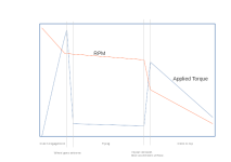
I get what you're saying, and there's plenty of merit in formally analysing the problem - if it was for a well paid job that's likely what I'd do. But for this I'm quite happy to just jump in based on mental analysis. But here's a very rough sketch of the concept in a "splat to a face" - bike starts stationary, RPM is high, clutch is released to launch the bike (rotation around rear axle and just enough forward movement to carry to the obstacle). Bike goes airborne & rotates past vertical so rear wheel extends forward & lands on obstacle, gains big traction as tyre flattens onto face and drives straight up.
It's by no means meant to represent reality, just an indication of the basic form of the profiles. I didn't show time - this might occur over about 1 sec +/-.
Splat torque RPM profile.png

The fundamental concept is pretty simple and the maths shouldn't be too hard either.

In it's simplest form it's a PID over current command to achieve a set RPM target. The RPM target is inversely proportional to time since throttle closed. With a hard limit to the maximum current supplied.
The PID variables, RPM time constant and current limit are variables that will need experiments to resolve.

The current limit will somewhat replicate a flywheel's fall in energy as load is applied - if load exceeds the current limits ability to compensate then RPM will fall. Definitely far from accurately, but by matching that to various obstacles the basic concept can be proven out.
The PID will do what PID's do - smooth response out. There might need to be different PID factors for attack and decay, but KISS for now.
The time constant will to an extent reflect the total energy in a flywheel - longer time constant approximately equivalent to bigger flywheel.

If it can be matched up to be reasonably effective on a variety of obstacle types then it's worth spending time making it more sophisticated. If not I'll need to reconsider the whole approach.

In an ideal world you'd be able to keep the throttle open (partly or fully) and so alter the output, but that's going to be considerably more complex to resolve than just having a simple throttle cutoff point to read. In real world we often ride with a trailing throttle - progressively closing the throttle as you ride an obstacle.
One thing at a time for now, prove out the concept before burrowing too deep. After all, the alternative is just chuck on a hunk of steel and be done with it, I know that works extremely well and is cheap, quick and simple. This is just to scratch an itch.

Oh by the way, very nice looking Greenspeed conversion you've done there!
 
Last edited:
This is just to scratch an itch.
With a profile, and boundaries, you can now design a controller to deliver.
I told my own approach to give a path to working out a physical target to instantiate, but it seems you can handle that.
I've been asked by my bicycle fabricator to work out a control system for a motor design he has (as he's not good with computers) so I'm going to bow out here.
I'm starting with a Raspberry Pi. I have no idea yet if that's needed for what he wants, but it's general enough that it won't stop me coming up with something that does tell me what's needed. I'm not shipping product.
I'll read along though. Best of fortune.
 
I think you need to remap your problem to a paradigm that motor controllers understand. High tech motor controllers control current, which is torque. The rpm control is an abstraction on top of that. I do not think you actually want to control RPM in any way, you may think you do, because you have previously dealt with controllers that do that, or cheap duty cycle controllers, but... you probably do not.

From your graph above, you might consider that what you want is:
Throttle sets the max torque (current), 0-100%
Clutch is also mapped with an analogue input, and places a limit on the max torque - 0-100% of the throttle output.

If you really want to simulate a flywheel, you can put an integrator on the throttle that is gated while the clutch is open (squeezed lever) and decays when the lever is released. Feed that into the torque (current) command.

At that point, you have a system that I think behaves as you want it to. No rpm involved.

As soon as you move into rpm control world, you have a second PI controller that is not well conditioned compared to the original current controller.

If there is no physical flywheel, you cannot get bursts of torque beyond the motor/controller capability, regardless of the control method. If there is a physical flywheel, it does the rpm control for you by simply applying low torque command and letting it free spin.

If you have a physical clutch, you probably also need a physical flywheel; most motors are optimised to have very low inertia, so the gains from spinning up the motor as a flywheel are small (or require huge rpm that then wrecks the clutch) or you are going to be trying to very precisely balance the clutch and motor torque command...
 
Last edited:
you may think you do, because you have previously dealt with controllers that do that, or cheap duty cycle controllers, but... you probably do not.
I've never used a speed based controller except setting my Nuc to that just to see how bad it is. It's bad.
If you really want to simulate a flywheel, you can put an integrator on the throttle that is gated while the clutch is open (squeezed lever) and decays when the lever is released. Feed that into the torque (current) command.
That's only a slight improvement over the well tested version without the decay feature. It's rubbish. EM used that for a few years before they gave up on it except on their cheaper bikes. The response out of the controller just doesn't cut it. Maybe it could, but not with any controller currently available.
It's only the falling side of the graph that I want to try managing, not the rising side. A clutch and flywheel will so far exceed the ability of any controller I might get my hands on for the rising side, I'll definitely retain a clutch & flywheel, but perhaps I can electronically adjust the overall response during the falling side.
EDIT: I realised that was confusing - it's only the initial rising side of the graph I don't want to control, the clutch release. The second rising slope should be controller driven.

If there is no physical flywheel, you cannot get bursts of torque beyond the motor/controller capability, regardless of the control method. If there is a physical flywheel, it does the rpm control for you by simply applying low torque command and letting it free spin.
Yep. So I fully expect to add the electronic solution as an adjunct to a real flywheel & clutch.

If you have a physical clutch, you probably also need a physical flywheel; most motors are optimised to have very low inertia, so the gains from spinning up the motor as a flywheel are small (or require huge rpm that then wrecks the clutch) or you are going to be trying to very precisely balance the clutch and motor torque command...
Absolutely. That's what Dragonfly and to an extent EM don't seem to have fully grasped - a clutch without a flywheel is almost pointless, and a flywheel without a clutch is downright dangerous.
 
Last edited:
I think at some stage, you need to accept there is a degree of programming and tuning required for this. As you observe, a physical flywheel and clutch is basically a requirement for the violent acceleration you want. In terms of controller, in torque mode this is not hard, currents can be controlled within 100us time frames - 0A to 500A with a 20uH motor and 100V battery is possible in low 100s of microseconds with a well set up VESC or my firmware for example, and if it is set up correctly, there is no reason for it ever to trip due to acceleration, however violent. It is however, a bit of a nuisance to get set up.
 
I think at some stage, you need to accept there is a degree of programming and tuning required for this.
Absolutely. And having now considered the options I've decided it's a dead end for me.

I looked at doing a micro to sit between throttle and controller and do the manipulation of the throttle signal to the controller. That looked like it might just be doable by a nufty like myself given enough time.
But after talking with an professional electronics type who has real-world experience with both programming embedded controls and manipulating e-trials bike throttle signals, I've gone completely off the idea. Well over my head.

Delving into the depths of VESC or your controller are similarly going to be a pointless exercise. I've barely got the vaguest idea of where to start. Who know what sort of a mess I could make of that given enough time.

It's a shame, it would have been an interesting project.
Seems like lumps of steel are more my level of complexity.

Thanks for the input.
 
Back
Top