APL's DIY axial-flux motor

I found this video of a magnet being water jet cut, and it looks feasible,.. of course some before and after magnetic
test would have to be done.

The video is of two guys horsing around, so if you don't want to wade through it, just go to 4:36 and again at 7:07.
Obviously, some preparation/mounting and positioning would be needed.

https://www.youtube.com/watch?v=lXVmEPU1L1k

Might even be fairly cheap, if all the magnets were lined up so that all of them could be cut in one pass. It would only take
a few passes, with mostly 'set-up' time. For segments anyway.

I know a few people locally with access to one, so when I have time I'll look into it, and see what kind of pricing is involved.
Plus, theres the Big Blue Saw add, here on the ES, in the services category.

A little too late for this project though, as I'm a little over half done. But it's good information to have, for future projects.
 
Also, theres the possibility of making a DIY water jet machine, or at least, a straight line cutter with a screw drive.
Maybe convert some old 3D printer parts. Would be slow, but it would work.

I know, you can tell,.. I'm a DIY guy. :lol:

Anyway, could be useful for cutting out other things as well. :?: Something to think about.

This guy uses a 3000 psi pressure washer, and has very good results; https://www.youtube.com/watch?v=qAIDFaKhcZE
 
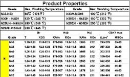
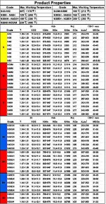
Found this chart for magnet properties, and can be found under many E-bay add's. I don't remember seeing it before,
but it shows the temperature range and typical T-strength of the Neo-magnet materials.

Of course, N52 is the worst, as far as temperature goes. Just my luck. But it's interesting to see the letter designations
for temperature ranges. Anything with a M, or H, at the end is rated for a much higher temp.
N33AH is rated at 446 degrees!

201712131628334735205 copy.jpg

201712131628334735205.jpg

Thought that it would be relevant to show here.
 
APL said:
This guy uses a 3000 psi pressure washer, and has very good results; https://www.youtube.com/watch?v=qAIDFaKhcZE

That's pretty cool, but looks a bit messy. For a straight line cut, you could just advance by hand using a screw drive. It cuts glass, which is pretty similar to the magnet material. No worries about demagnetizing the magnets. :thumb:

The magnet chart is very relevant. N52 is the easiest to demagnetize. I put some N52 magnets through a steam sterilizer (270F) and they came out completely demagnetized. Stronger is not always better for motors too. Higher flux will create more iron losses but gives the most potential torque density.

There have been steady improvements in magnet material over time. Stuff you can buy today was not imaginable 50 years ago.
 
Yes, I fear that just the scoring with the Dremel disc is heating them up too much. They still have good power, but not
as much as original. I'll keep going, and see what happens.

I have been thinking more and more about building a cutting machine. Not right away,.. but later this summer maybe.
It would be nice to sit on the porch with a beer, and just watch the darn thing cut magnets out in the yard. :)
It would only take an hour or so, instead of two weeks.

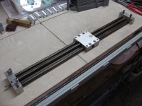
I have a linear slide thats perfect for the job, thats been laying around waiting for something like this. And some stepper
motors from a basket case printer. Just need simple a motor controller from the Bay, and it should work.
Once the correct speed is found, I shouldn't have to touch it.

Linear screw drive..jpg

Make it so that it sits on top of a 50 gal barrel, and make the table with a 2mm slit the length of the slider, and she's done.
The pressure washer can be begged, borrowed, or stolen,.. or just rent one from a rental place for a few hours.

The only real cost is the nozzle assembly, and they can be had on the Bay for a little over $200. I'm sure if I keep looking, I
can get that price down too. Since it will just be used for magnet segments, it should last virtually forever.
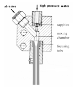
Basically, it's just a sand blaster, and not complicated at all.
It will cut them perfectly, with no losses, and the magnet worries of building motors would be eliminated.
Now, if it will just work. :wink:

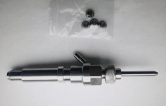
Abrasive body and mixing nozzle..jpg

1. Abrasive nozzle components.png
 
Wire EDM might be another way to cut the magnets nicely. I've seen some DIY EDM setups. EDM is very slow though.
 
Thanks Ribiero, where theres a will, theres a way,.. hopefully it will work, but won't know until we try. :thumb:

EDM is another idea that might work, your right fechter, I've been holding off on the idea, because I don't really
understand it yet, and it seems a little more complicated.
It does have the advantage of providing a controlled depth to a cut though,(?), and appears to be very quiet, and
in-shop worthy. Fluid cooled, so heat is probably not an issue.

Instead of cutting, it might be used to make a really precise score though, for easy breaking. Otherwise, like you say,
probably slow, for DIY anyway. I'm sure an industrial one moves pretty fast.
I'll have to do some digging in to it, I thought I saw a few different kinds.

The water jet is fairly straight forward, and simple. I think the sand is cheap, and it can cut anything as long as it's
not to thick. So it might be more useful.
 
Absolutely APL, I noticed earlier you had a green bandsaw in your workshop. Is it the type with a coolant spray and recirculating tank? If it is have you considered adding bags of ice to the tank? I would tape the faces of the the magnet then sandwich between aluminum plates. Possibly add ice to the top plate. I defer to your machining experience,and cannot test this myself. I see this as a heat removal problem. I will have to Google EDM, to me it means electronic distance measurer.
 
fechter said:
Wire EDM might be another way to cut the magnets nicely. I've seen some DIY EDM setups. EDM is very slow though.

Yes but i think there should be a tiny gap between cutting wire and material and if it is magnetic it could be problematic when the magnets attract it.
 
Interesting to see all the different types, I wasn't aware of the ram type. The continuous wire saw is interesting, and
would probably make a good cutter. It's unclear as to whether the wire is re-used or just consumed. It's also interesting
to see that very small holes can be drilled in super hard steel.

I didn't think about the magnetic attraction aspect, and it could cause additional problems, your right. Plus, high current
going through the magnet may not be a good thing, but would have to be tested.

I'm not sure about the saw Ribiero, I know that it doesn't cut well with fluids though, and tends to just slide, and not cut.
Sandwiching the parts between aluminum, and cooling it, is interesting though, instead of ice I could use compressed air,
I'm not sure how it will cut magnets either, I'll have to try it. Theres a problem with high blade pressure though, and the
ascent would have to be controlled, although the aluminum would help with that. Thanks for the idea. :thumb:
 
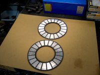
Finally finished the rotor PM's, theres a few that need replacing, but there it is. Now it's on to the dreaded bonding process.
At least it 'looks' like it has a chance of hauling my butt down the road. :)

V2 PM's finished..jpg

We shall see, if not, I can always make new ones. It is possible to put the big dog trapezoids on here, with 5mm overhang
over the end turns, but the 16 PM's would be full pitch, and touching end to end.
It would probably be best to re-design for those guys.
 
That looks great. A little jaggedness along the edges won't matter much.

Try to find a huge magnet you can place on the back side of the iron when gluing. I strongly suggest a practice session with expendable pieces. If you don't have any big magnets, try stacking a bunch of the smaller ones to make a thick magnet.

If you need to clamp the pieces down during glue curing, you can use polyethylene between the magnets and a piece of wood so the glue doesn't stick.

Be sure to wear rubber gloves when playing with the glue.
 
Well, actually, I am. I'm just getting started. I don't plan to do every build on here, but I'll show them off.
It's called, "having a hobby". And every hobby has it's specialized tools. Many times you have to make them.

I like the idea of making my own cutter. It solves the trapezoid magnet problem that axial's have. I can make them
big or small, and in any number I want. Totally rocks! Plus I can cut other things like glass or hardened steel.

Fixed income,.. I don't want to buy customs every time, and these first motors are probably going to get shelved.
A head unit is all I need, and it's not that much in the long run.

Now I can move on to the next most expensive part of the build,.. the cores. Need a easy and cheap way to make
them too. Thats why were using SMC,.. to see if it can rival laminations. Thats the main test of this motor.

People have different ideas of what DIY is anymore. It seems more like 'assembly' of store bought parts these days.
And how fast you can do it.
Being raised in mid 50's, we made everything, and it was respectable to have hundreds of hours into a hobby.
We couldn't wait to get out in the spring, and see the R/C planes that the big boys built over the long winter months..
Probably why I'm the way I am,.. it's a Boomer thing. :D

Larsb, look at those things,.. they're a work of art! 8)
 
Don’t think it’s a boomer thing :wink:

I can relate to the ”everything is interesting” part, however there is only so much time. Maybe you just have more of it than i do.

I’ve come to a conclusion that my focus is on either the interesting stuff or the stuff that takes me somewhere. Didn’t see spending some hundred hours on a half decent water cutter being that in your build
 
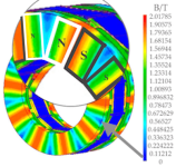
Fechter, Your idea of using a big magnet on the other side for bonding is a good one, but it got me thinking. Instead of
using thick back iron on a motor, it might be plausible to use magnets in between the PM's on the back side.
Between the split in the flux pattern.

There seems to be a nice square area there that some standard 10x40mm magnets could be placed side to side N/S.(radial).
Could be lighter than a thicker ring of steel, and might contribute at least a little to the total flux.
Not quite Halbach, but sort of. Thing is, they could have more of a ubiquitous fit, rather than a precise one.

Maybe go with even thinner, or no back iron at all that way, just composite.
Food for thought, unless I'm missing something.

Axial flux distribution in back iron. copy.png
 
Needed to take some time out to get some core material ready for machining, so that once the bonding, anodizing, and
a few other loose ends are done, they will be nearing completion.

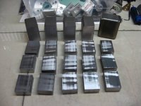
Once the original block of SMC was marked out, I got a little shock, realizing that it was going to take the entire 20+ lb
block! The cubes are oversize, and close to half of that will be machined off, but it will still probably be close to 10 lbs.
I can see where every millimeter of the core design is important, weight wise, and one should design for minimum.
Just need to know what minimum is.

SMC stock..jpg

I also took madin88's advice and removed the lip at the top and bottom of the core, so that the end turns are out of the
circuit, and made the slot longer in the back for more area. Although the slot could still use more area, it equates to
6mm thick of wasted steel, so I'd like to figure out a way to use a thinner stator plate, to reduce that.
Could maybe use thick material from the axle to the cores, and then a thin disc just for the cores.

New core..png
Placing the end turns inside the circuit, means less steel and less copper, so maybe thats why it's often done. Lighter,
cheaper, and shorter wire.

I'll have to give a lot of thought to making the core as light as possible, any improvements will be multiplied 36 times,
but for now we have to start somewhere, so this will have to do.
 
In assessing the core weight, I'm looking closer at the tooth tip, sometimes called brim, or lip, and overhang. On the
present design core, it accounts for a large percentage of the weight. It's not just the tip, but the whole face area that is
as thick as the tip profile.

On this core, a 4mm thick steel face, 36 times, equals a piece of iron roughly five inches long and equates to about 2 lbs.
of motor weight. What benefit of the tooth lip justifies the extra weight? The lip also makes machining SMC very
difficult, since it is fragile. On laminations, it's easy to include, because they're stamped

Total tip steel - 13 cm.  2 lbs..png

I see lots of open slot axial motors that don't use the tooth tips, so at what point does it become necessary? How bad can
it be if some motors use it and some motors don't?.
It's my understanding that the use of tooth tips, or simi closed slots, is primarily to even out the cogging effect, and open
up the fring flux in the air gap. They reduce eddy currents in the PM's and back iron as well. Plus, it keeps the wire in the
slot.

I can see where the use of tooth tips might be more likely in a low slot/pole count motor, or a high speed motor. But
generally, cogging steps are a product of pole count, and the more steps, the smoother the effect.

The question is, do we really need these tips, or can we get by without them? And at what cost.
 
APL said:
People have different ideas of what DIY is anymore. It seems more like 'assembly' of store bought parts these days.
And how fast you can do it.

Hear hear ! For me too the process of the build and the research going into it are more important than the end result... else i'd just get an ebike in the store.
 
The brim part was supposed to more than compensate for the slightly higher losses in the core material compared to silicon steel. Reducing the brim area will lower the efficiency somewhat. Their reasoning was that by having a brim, the same total flux could be achieved with less length of copper, thus reducing the copper losses. Exactly how much difference this makes might be calculated.
 
Thats good to know, I didn't see it in my searches. The question is still how much, and as usual, a test will probably be in
order, as every situation is different. I might be able to do that test on this motor later on though, if it isn't too hard to
do. (it's my obsession with weight) :wink:

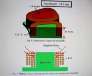
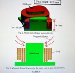
In my search for answers I returned to the Hokkaido University paper shown previously in this thread, which deals with
this very issue, and found some interesting things. A flat top, open slot core is the worst, as the PM flux directly induces
the copper windings.

IMG_2219 (1) copy.jpg

It's better to use a 4mm core extension past the windings, to escape this, and even better yet to add a brim over the
copper.

IMG_2218 (1) copy.jpg
IMG_2220 (1) copy.jpg

So if one needs to use a 4mm extension, then weight savings are not reduced that much, and adding a brim is going to
add very little more.
However, that being said, the chart showing the losses per-rpm of all three types, shows basically zero losses up to 800
rpm. This motor only spins at 400 or so, well below that.
So the question is still somewhat open blow 800 rpm.

IMG_2221 (1) copy.jpg

Taken from the Hokkaido university article; https://eprints.lib.hokudai.ac.jp/dspace/bitstream/2115/67264/1/Final_text.pdf
 
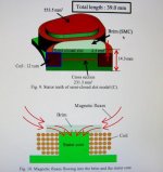
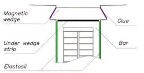
Then theres the use of magnetic slot wedges, for open slots. Slot wedges have been in use in radial motors for a long time
as a means to keep windings in both stationary, and rotating masses. And are usually found in high slot count machines.
Usually made out of long, non magnetic polymer strips, that slide into groves, machined in the tooth tops.

Open slot, magnetic wedge..jpg
https://www.ee.co.za/article/using-magnetic-slot-wedges-hydro-generators.html

But it was found that by using 'magnetic wedges', a form of SMC, that a good reduction in losses were achievable. Looking
at the composition of the wedge material, it has a relatively low iron content compared to SMC,.. at only 70 percent.
The rest is binders, simular to the epoxy core I made in the beginning this thread.
http://www.camawi.com/four.html

Anyway, I have to wonder if this might be applicable to an open slot axial, with a fairly flat top core. As a way to reduce
weight, and make the cores easier to produce.
Thin strips of magnetic material over the copper windings could be held in by PCB, or 3D printed caps.

It's too bad that the new 'iron content' PLA for 3D printers is not quite magnetic enough, as it could be very easily used for
this purpose. Perhaps it will improve.
https://www.proto-pasta.com/products/magnetic-iron-pla

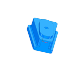
Heres a concept for a simple open slot core, that uses spacer plugs to transfer flux and locate the cores. The idea is that
it may be easier to make 18 spacers, than it is to machine 36 cores, and the spacers can be changed for different stator
carrier thicknesses, while the cores remain the same.
The spacer can be any shape and size, I just show a slot because it was easier, and should be longer.
They can also be bonded into the carrier, for a solid fit, and the cores easily removed.

Weight reduced core..png

Not that I plan on changing the current design, just tossing ideas around, for future projects.
 
Back
Top