APL's DIY axial-flux motor

I've also been revisiting the idea of pressing your own cores DIY style. It occurred to me that the atomize-coated iron
powder that SMC is pressed from might be purchased and pressed into a machined steel mold, using a hydraulic jack and
a shop press. Easier said than done, but still might be possible.

It wouldn't have the same strict technical characteristics of factory SMC's, such as Somaloy, but may still be usable for
home brew motors. A single mold could make all the cores,.. and in an intricate shape. Of course, there are lots of
problems to overcome, such as type of binder, mold release, pressure regulation, etc. I don't know too much about it yet,
but the benefits of being able to do so would be great, so it might deserve at least a good look.

As it turns out, the powder may be available, in bulk from China, but the minimum order is 50 kilos, (barrel), at $10. a kilo.
($500. per drum) Certainly could make a lot of motors out of that! :lol:
But I haven't looked around much, just exploring possibilities at the moment.

https://cisri-int.en.made-in-china.com/product/qMdxKaAjETIZ/China-Soft-Magnetic-Alloy-Powder-SMD-Fesicr-Amorphous.html

One problem I see, is that the standard SMC material is pressed at a very high pressure,.. on the order of 600 to 800 MPa's,
or megapascal's. 600 MPa is equal to 87,022 lbs. or 43 tons.
Hmmm, I might be dreaming a little too much. :wink: But there are hydraulic shop presses that will do 50 tons, for not
too much money. Big enough to do a 600 MPa part. (Harbor Freight, Northern Tool)

It's still a little unclear as to whether that kind of pressure is all that necessary for bonding, or to get the desired specs
needed. They don't appear to use any epoxy binders, unless it's in the powder mix. If not, then it appears to be just the
pressure that bonds it together. :?:
30 second compacting video; https://www.youtube.com/watch?v=lJ22svZFGKc

Somaloy specs.; https://www.hoganas.com/globalassets/download-media/sharepoint/brochures-and-datasheets---all-documents/somaloy-3p_material-data_june_2018_2273hog.pdf
 
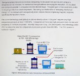
Found some info on the production process, a little outdated (2016), but it shows the basics. Theres a heat treatment
and cure step that helps bond it and achieve the desired specs. 1hr at about 300 C.

SMC mfg process .jpg

Taken from "Magnetics"; https://magneticsmag.com/insulated-iron-powders-smc-current-state-and-future-possibilities/
A good article explaining the process.

So, looking more like a fantasy for now. (but not completely out of reach if someone really wanted to pursue it)

What I really need, is a source for Somaloy, or at least a sample, to see how strong it is, and how it machines. But as of yet,
I have found none. After working with the Micrometals iron core material for a week, I'm finding it to be extremely brittle,
and I don't think it was designed to be machined.
 
Really! Thats awesome. I was wondering if you might have better sources, as a machine shop. The point is a bit mute
though, if you say it machines about the same, too bad, I was hoping it was stronger. This stuff machines like packed dirt.
Still, good to know that at least it may be possible to try some, for whatever reason, or in case this experiment
fails. To bad about the price.

Seems like everything is a one way street with DIY motor cores, and I'm going the wrong way. My kingdom for a core!
I'll keep tying though, a little cleverness will go a long way,.. and theres always air core motors to dig into yet. :)

Comparing some specs on the two, I see that the density is pretty much the same, but slightly more in the Somaloy, which
might be reflecting the slight strength difference.
Micrometals density; GM/Cm3 - 7.2
Somaloy density; GM/Cm3 - 7.5
 
A few pages back I was asked if I was planing to use a steel ring for the stator core carrier, and I replied that it would
cause a 'one turn' short around the cores, much like the aluminum carriers in the last motor build did.

That is, it would act like a large single turn of wire, around the core, that was soldered together on the ends, and act
like a generator with the output leads shorted out, causing nothing but heat.

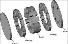
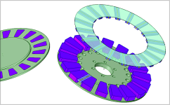
But now I see a good number of double sided stator designs, with dual coils, and a center iron arrangement. The center
iron is acting as a back iron obviously, but wouldn't the short effect still be present?

Center iron axial.jpg

The question is,.. if we make the back iron thinner and thinner, at what point does it become a one turn short, if at all?
Or is it because the iron is not really going around the cores,.. only between them?

Am I missing something? Because if I can use a thin steel ring to hold the cores, then the 'partial' through flux problem
between the cores is solved, and it saves the slot machining on both stator and cores, and makes the motor thinner.

Not used as back iron,.. only to hold the cores, and transfer core flux.
 
APL said:
The question is,.. if we make the back iron thinner and thinner, at what point does it become a one turn short, if at all?
Or is it because the iron is not really going around the cores,.. only between them?

Am I missing something? Because if I can use a thin steel ring to hold the cores, then the 'partial' through flux problem
between the cores is solved, and it saves the slot machining on both stator and cores, and makes the motor thinner.

Not used as back iron,.. only to hold the cores, and transfer core flux.

I think that it would only act as a one-turn-short if alternating flux would flow through it from one side to the other.

The motor you posted pics probably works different, more like two stators of quasi independent motors which were put together. Think about half the stator belongs to the left coils and rotor, and the other half to the right coils and rotor. Two independent systems where the flux from the left rotor keep staying on left side and flux from the right one on right side. In such case it would be necessary to have back iron behind the cores or stator teeth (just like usually such motors have).

To answer your question i am sure that it would make things worse if you use a steel ring to hold the cores because alternating flux is going through it from one side to the other.
 
I'm probably going down a dead end street, but I'm trying to understand what the deal is.

Laminated, or SMC ring. I thought about that, and I figured that it would be needed for eddy current-hysteresis
losses during pole switching. But that the one turn short might be a different effect, and occurs in any metal that
surrounds a core. But I'm not too clear on it yet.

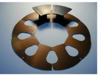
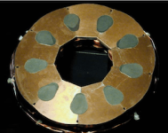
Looking back on this motor design, shown here many times, that has a laminated back iron, but used in a radial position,
instead of laminations wound at a right angle like most stator irons. It shows segments, but it doesn't look like they're
separated when assembled, and act as one piece.

2-Figure3-1.png
5-Figure7-1.png

If this can be done, and two of them placed back to back, like madin88 said, then I see little difference between that and
a single disc, if it was made from lamination steel?

Madin88, I think your right about the center iron's thickness as making a big difference. But as it gets thiner, and thiner,
then the flux moves easier between the two cores, My thought was, that if a thin enough disc of steel was used, at some
point it might be relatively invisible in any direction but straight through. Say maybe, 1 - 2mm thick. We only need enough
thickness to hold the cores securely, and steel is pretty strong. Probably wishful thinking though.

Since the disc only goes from one core to the next, and doesn't surround a core, I don't see where a short is from, and the
steel is to thin to carry any meaningful flux between the cores.
 
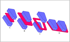
Thinking about it incrementally, The small section between the stator cores 'A', is obviously OK, but the large section
in 'B' is questionable, and the circular piece 'C' is definitely a one turn short. The last one 'D', is also in question.

Back iron short..png

After doing some experimenting today, with magnets and thin steel, I find that the flux doesn't want to travel through
the steel very much. Even the thinest piece has the same effect. Some magnetic flux gets through, but it's a small
percentage. So with that, the idea is busted.

Stainless steel was invisible though, and it may be that an .065" disc of that would pass enough flux through, to complete
the magnetic circuit. The 1T flux of two Neo. magnets can be strongly felt, even at a few centimeters apart.
Carbon fiber may be strong enough as well, but both these materials can have eddy losses. Still, it may be negligible.
These cores have a lot of area, and when placed back to back .065" apart, they could pass a lot of flux.

Not exactly the best way to do it, and may produce a soggy circuit, but build-wise, would make things much easier.
In effect, I guess it would be the same as widening the air gap, :?: , but perhaps then the air gaps could be smaller.
Well, can't blame a guy for try'n, I'll keep on rolling it around.

The eddy current ability of carbon fiber has been thrown around here many times, but I've never seen it being used in
a build, or any info one way or another on it, until I found this thread by Shane Colton. He has lots of interesting builds,
but it's a little hard to navigate through his blog, so I'll include the three pages here.

http://scolton.blogspot.com/2010/02/thought-exercise-leaf-motor.html
http://scolton.blogspot.com/2010/02/leaf-motor-blitz-everything-but.html
http://scolton.blogspot.com/2010/03/leaf-motor-spin-up.html

LEAF_collapsed.jpg

An interesting air core axial, and a lot of good information on determining torque from scratch, in the design stage.
The motor ultimately suffered from some losses, but it wasn't attributed to the carbon stator faces,.. but internal
copper.
 
I think the iron in your picture above will act like a one turn short in all cases. If you slot the iron radially to break the circuit it will be better, but you will still have some eddy currents in the iron. Something non-conductive is really what you want.
 
Can't break the laws of physics I guess, and there aren't any materials strong enough that are not conductive, except for
glass, and ceramics. Plus the idea of a flux gap carrier is just added inefficiency to an already slightly compromised SMC
core, so I guess I'll shelve the idea, and concentrate on improving the current design.

I think that the .250" Garolite carrier that I'm using is a bit thick though, and the core mount ring section could probably
be reduced by half, as long as it keeps the thicker inside section. Resulting in 3mm less core steel. We'll see how this one
works first.

I finally finished prepping the SMC blocks for the cores, to be sent off and machined. I hope Coleasterling has a better
time than I did with it. The old grandpa Cincinnati mill, and worn out cutters I have didn't help,.. I'm sure.

But now I can get back to bonding the magnets to the rotors. On that note, I found this article that uses round magnets
on the rotors, but in a low pole count fashion, that might be of interest. Grouping larger numbers in less poles is
something I didn't think about. The magnets are 2cm wide and 2cm tall, and are set into Duraluminum, which is done to
shield some magnet losses. (odd) Apparently it uses an insulated wire core too.
The motor's no punk,.. 245v, 25 Kilowatt, and 10,000 RPM.

Ironless-axial-flux-machine-scheme.jpg

https://www.researchgate.net/figure/Ironless-axial-flux-machine-scheme_fig5_274744551
 
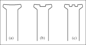
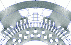
From time to time I see a motor, with a stator tooth that has a groove down the center of it, and wondered what it was
for. After looking around, I found that sometimes grooves were used to get the motor to move in one direction more than
another by placing a groove towards one side of the tooth. But I suppose Hall sensors solved that.

Digging into it more I found that one term for a center groove is bifurcation, or a bifurcated tooth. Be sure to add 'stator'
to the search title, or it will show a lot of bad dental images :confused:

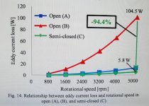
The use of tooth tips, or simi-closed slots, is the most common and preferred way to reduce cogging torque, but by
putting a slot in the middle of the tooth, it can also add to cogging reduction. (radial direction on an axial)

Single, double, or even several grooves have been used, and in some cases, a 'T' slot is used. As far as how wide and how
deep the tooth slot is made is investigated in these papers, sometimes with good results,.. as much as 40 percent gains.

Bifurcated stator tooth .png
Motor Art.gif

However, as usual, I suspect that there is no free lunch, and something, probably torque, is reduced as well. interesting
though, and deserves a mention, and a looking into.

T slot PDF; http://www.jpier.org/PIERM/pierm66/10.17110902.pdf
'Images' link to other articles; https://www.google.com/search?q=stator+tooth+bifurcation&tbm=isch&ved=2ahUKEwis9ZbU6L3oAhXDCd8KHUfvD6wQ2-cCegQIABAA&oq=stator+tooth+bifurcation&gs_lcp=CgNpbWcQDDoECCMQJzoHCCMQ6gIQJzoECAAQQzoCCAA6BggAEAgQHjoECAAQGDoECAAQHlCgQ5YrpsPYNvVD2gBcAB4BIAB4gSIAdR2kgENMS40LjE4LjEwLjguNZgBAKABAaoBC2d3cy13aXotaW1nsAEK&sclient=img&ei=7Zl_XuzKNMOT_AbH3r_gCg&bih=1012&biw=1680&hl=en

I haven't seen it done on an axial motor though, and wonder if it might be worth a try one of these days. :wink:
I suppose any cogging reduction would show up in the no load speed.
 
Interesting but certainly seems complex. It seems like there would be a sacrifice of torque density, but I didn't read the whole paper.

I think your current design looks pretty good.
 
Yea, it probably needs FEMM be done right, or a lot of experimenting. There is a reduction in torque. From 2.5Nm to
1.8Nm. The use of a 'T-slot' is a little extreme. After reading it a few times, I thought that it seems like some thing's
are lost in translation. Images don't appear to match the text, (flux concentrations), and other things seem amiss.

T slot torque reduction..jpg

I've noticed other papers with image mismatch, or text problems too. A few posts back, I show a chart that show's the
difference between a flat top core, extended core, and a brim added. 'A' was the worst, and 'B' & 'C' were much better.
But the chart shows 'B' as being the worst, the colors are switched.

IMG_2221 (1) copy.jpg
Always something to watch out for.

Theres other papers on the simple standard groove though, instead of the T slot, in the images link, but they required
a download that I couldn't post.

The loss of torque is not as bad on some of the simpler groove designs, and I suppose there are situations where less
cogging torque is more desirable than the total torque losses. Maybe in a really high slot number motor.
Theres might be a middle ground combination that provides good overall results.

Probably not going to be a game changer on a simple bike motor, but I thought it's worth a mention at least, since I
haven't seen it talked about anywhere else.
 
Yeah, toothed stators are usually used on stepper motors along with a toothed rotor to gain stall (holding) torque, usually at the cost of rpm.
 
Interesting, admittedly, I never really looked at how stepper motors were built, I see now that they use slotted stators
and rotors. But like you say, for a different reason.

Rotor and stator, Stepper-Motor.jpg
 
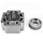
SMC iron, band saw's and belt sands like a dream, but machines badly, so I'm still trying to figure out how to use straight
cut trapezoid cores, because they can be more easily made DIY. Or they can even be water jet cut. At least, for future
motor projects. Another advantage they have is that the coils can be slid on and off.

Expanding on the idea of open slot magnetic covers, I wondered if the SMC could be cut small enough to make the tooth
brims, without falling apart, so they can be incorporated into the covers. In effect, making the straight cut cores brimmed
again.

Open slot & brim covers.png

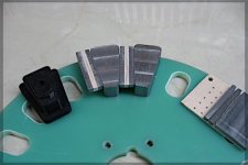
I did a quick experiment by cutting a 4mm slab of core iron, and gluing it to a piece of PC board for support, and then
cutting it into the 4mm brims. I was surprised at how easy it was to cut really thin pieces that way, and the idea of making
them any size becomes feasible. I can space the pieces for different tooth gaps, by using a different thicknesses of glass
board before bonding and cutting.

Changeable open slot winding covers..jpg

Bonding them all to a thin ring of Garolite, makes installation easy, and serves to keep the coils in place, plus protects the
core faces. Different brim sizes, gaps, and shapes can be experimented with, and changed out with different ring
assembly's. I'm not sure how good that will work in reality though, as they would need to all fit fairly snug.
Maybe a layer of silicon in between the pieces.

Another idea I was rolling, is to glue the carrier spacers in place, (top left image), and then glue the cores on top of them.
It makes the stator stronger overall, and since no bolts are needed, it makes a no-stress mount. All this is good for SMC.
Might be easier to mill the shapes in the core backs though, since they would only be 1.5mm tall, on the 1/8" thick stator
idea. I'll need to try it and see.

I never liked the idea of bonding cores in before, but the advantages are pretty good, and at least the carrier assembly can
still be changed out.

Just some thoughts on possibilities.
 
Motor work has been a bit strained the past few weeks,.. with the current world's problems coming to all of our
doorsteps, :( , and spring bringing outdoor projects in demand. 

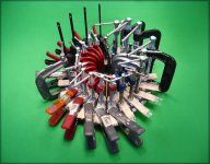
The preparation needed to get these magnets bonded was immense, and there always seemed to be one more thing
to do.  But I was finally able to get one rotor done.  Took every C clamp in the shop though!  I'll have to work on getting
the right sizes in the future, and making a stand for the process, witch would have really helped.
I decided that it would be better to just glue them all at once, to make sure everything fit, and have the option to stop,
clean, and start over.

Clamped!!.jpg

Things went fairly smooth though, and it wasn't that hard to force the middle magnets in place after all, other than once
they get glue on them, they become miserably slick, and hard to handle. Theres no way to be nice about it, the glue gets
everywhere, and on everything. Good thing I used some '4 hour set' glue, because I really needed the time.

Anyway, hope it all holds together,.. one down, one to go.

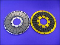
I weighed the two rotor assembly's, V1 and V2, and came up with only 37 grams difference.  So the mostly steel rotor is a
slight success over the aluminum one, as it has much more magnet area, is cheaper, and a little easier to make.

V1 & V2 rotor comparison..jpg
 
That's a LOT of C-clamps! Came out looking nice though. Small variations in the edges between sections won't matter.

I'd suggest placing the rotor in a large plastic bag until final assembly to prevent it from picking up magnetic debris that is hard to clean off later. With an axial rotor I suppose it wouldn't be that hard to clean if stuff gets on there but it can be a pain with a radial design. One little chip left over can ruin your day when doing the final assembly.
 
Yea, there were a few pieces that I wanted to replace but forgot, and once I started gluing, it was to late. Well, like
you say, it won't matter too much. Hopefully, if I get the water jet cutter going, the pieces will all fit perfectly.

I have to anodize, and mount the center hub yet, plus grind away the plastic ring, to let the vent holes breath better.
Don't know why I made that so thick,.. live and learn.

On the next version, I'll have to consider making the rotor all steel, and eliminate the aluminum hub. Make more, and
bigger holes, to lose the extra weight. It would breath better, and save a lot of machining.
 
Things are still moving along,.. the rotors are finished and painted, and the hubs are drilled for mounting. The hubs
and bearing caps are getting anodized,.. but the first try was a fail, so I get to do it all over again. :(
That stuff can be a real hart breaker sometimes. I learn many new lessons every time I try it.

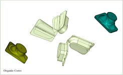
So I guess I'll just show some more 'over-thinking' pictures for now. I was trying to figure out a more organic core design
with minimal steel, and a more flowing, or funneling nature. Magnetics always take the easiest and direct rout, so sharp
angles and corners aren't very useful, except to hold wiring. But with a single layer winding, shapes may be overcome.
Still a work in progress, always evolving, and difficult to draw the way I want.

Organic Cores.png

The next idea was a return to the original V1 motor, with some of the new V2 concepts. (What?.. going backwards?)
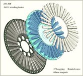
This time a 10" diameter is used, to make more space available, and get more torque, along with longer 60mm magnets.
A 27S/30P scheme is chosen, and gives a .94521 winding factor with a 270 cogging count. More poles, slower spin.
These changes would give it roughly 1/3 more slots, and 1/3 more tooth and PM area than V1 had.

High Pole count  V..jpg

The cores are simple SMC slabs, and bonded in place, for an easy build. The magnets are straight up bought and bonded.
No trapezoids, but the performance may be comparable anyway, it's not perfect, but the simplicity is good.
Just some more day dreaming ideas. :)
 
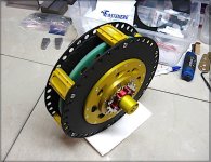
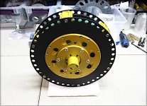
She's starting to rise up from the table, and looking more like a motor. I finally finished all the anodizing, and it turned
out looking pretty sweet, except for the spacers, which will need to be redone. Must have been a bad connection.
They have to get finish-milled for the air gap yet, so I might as well wait until that gets done first.

V2 anodizing 1.jpg
V2 anodize side view.jpg

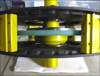
I threw it together for a quick fit check, and see that the bearing seats are a little too long, and they are hitting the
bearing caps, so I'll have to spin them down a bit, so that the bearings can come inward a few more millimeters. No biggie.
Otherwise, everything else is looking good, and she spins nice and straight.

V2 bearing spacing..jpg

I'll need to take some precise measurements for the outer fan segments, and start designing them for the 3D printer.
Other than that, I'm told that the cores will be on their way pretty soon, and I can get started with winding some copper.
So all is well in motor-land for the moment, and with a little luck, we'll see what this beast can do pretty soon. :)
 
It is starting to look a lot like an OEM-built motor. :)

When you get it all done, maybe I'll have the HI-Lebowski project instructions finished:
https://endless-sphere.com/forums/viewtopic.php?f=30&t=105711
and you can then build one of those to control it with. ;)
 
Back
Top