The easy test is to measure the voltage sag on the pack going from no load to full load. This will tell you a lot about the pack.
You are using an out of date browser. It may not display this or other websites correctly.
You should upgrade or use an alternative browser.
You should upgrade or use an alternative browser.
APL's V4 Cruiser Build.
- Thread starter APL
- Start date
APL
100 kW
- Joined
- Aug 6, 2018
- Messages
- 1,113
I just charged the battery so I'll give it another voltage sag test at it's best.
I added another B- plug that bypasses the BMS and shunt, so I can go either way, but it doesn't seem to make any difference yet.
I'll try it again with the fresh charge.
Cobbled on the other crap controller and fired it up, and it pulled a pathetic 500w, so that doesn't help. (Says it's limited to 42A.)
Feels like the twilight zone around here.
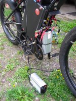
OK, it is pretty cobbled in, so I'll recheck it tomorrow, but it doesn't look good for this test, and I'll put the old controller back on.
So it's back to the battery, and I'm thinking that the one true test is to put a welded pack in there and see if it goes like a raped rat.
If so, then I have some tweaking to do on the battery box, or worse,.. I'll have to eat crow, and weld them all up. (But smiling because the bike rocks!) If not, then it's back to the controller, and the dreaded search, which isn't going well.
I have the two 10P 48v packs from last year that I know will work well, so I'll do a little surgery and make a 60v pack out of the two
by adding a 3S/10P.
I added another B- plug that bypasses the BMS and shunt, so I can go either way, but it doesn't seem to make any difference yet.
I'll try it again with the fresh charge.
Cobbled on the other crap controller and fired it up, and it pulled a pathetic 500w, so that doesn't help. (Says it's limited to 42A.)
Feels like the twilight zone around here.

OK, it is pretty cobbled in, so I'll recheck it tomorrow, but it doesn't look good for this test, and I'll put the old controller back on.
So it's back to the battery, and I'm thinking that the one true test is to put a welded pack in there and see if it goes like a raped rat.
If so, then I have some tweaking to do on the battery box, or worse,.. I'll have to eat crow, and weld them all up. (But smiling because the bike rocks!) If not, then it's back to the controller, and the dreaded search, which isn't going well.
I have the two 10P 48v packs from last year that I know will work well, so I'll do a little surgery and make a 60v pack out of the two
by adding a 3S/10P.
If it was a BMS issue, the BMS would shutdown power to the whole system.APL said:I added another B- plug that bypasses the BMS and shunt, so I can go either way, but it doesn't seem to make any difference yet.
The list of likely issues you might have are, in no particular order:
--battery sags in voltage so much that even at it's highest current draw on the controller, the total wattage is just too low. This will show up in voltage testing under load.
--the controller is not actually designed to draw as much current as it says it is.
--the load placed on the system is just not enough to draw more.
--the motor winding vs the gearing of the system is such that it never puts enough load on the controller to draw the power you're after.
--wiring/connections of the system somewhere between cells and motor is insufficient to pass the current required. This will show up as voltage drops (and heating) in the problematic parts.
I can't think of any other system problems that should cause what you see.
Cobbled on the other crap controller and fired it up, and it pulled a pathetic 500w, so that doesn't help. (Says it's limited to 42A.)
What conditions were the tests performed under?
APL
100 kW
- Joined
- Aug 6, 2018
- Messages
- 1,113
The conditions for the test are locking the brakes up and giving it full throttle usually, only this time I didn't need to, because the throttle is so soggy and the 500w max is obvious. (It acts like it's in the 72v mode, so I'll check that out today.)
I'll check the voltage sag too, but I have to get the Yantan controller back in for that.
Agreed, the BMS is probably not the issue.
"Controller current not as stated".. could be, and to be determined yet, but 80A advertised and less than 30A delivered is shameful.
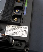
I'm pretty confident about the load I'm applying. Although maybe the 'short' original motor phase wires, or motor internals are
contributing to the problem. I don't feel any wires or connections getting hot or even warm anywhere, except for the motor itself, which gets only normally warm, and I've kept a close eye on all that.
(not cell temps though)
I've turned on both 75A switches on the fuse box too, which doubles up the wiring thickness, so that's not the issue either.
One scenario that I can see that could give all these symptoms is if the compression battery only had a few cells making contact on the end bus,.. but most all the cells are making contact in the rest of the battery.
Then the pack could charge normally, and pass the lower watt draws (500w) to give the rated 26 amp hours I'm seeing over a few days, but not deliver the high amp draws at full throttle because the current has to go through only a few parallel cells on the end. Pack would appear to be working normal, but wouldn't have the higher amp draw.
Which would make for a dangerous battery, since those few cells would be over worked,.. so I better stop riding and get this figured out.
Welded pack test seems like the next best move.
I'll check the voltage sag too, but I have to get the Yantan controller back in for that.
Agreed, the BMS is probably not the issue.
"Controller current not as stated".. could be, and to be determined yet, but 80A advertised and less than 30A delivered is shameful.

I'm pretty confident about the load I'm applying. Although maybe the 'short' original motor phase wires, or motor internals are
contributing to the problem. I don't feel any wires or connections getting hot or even warm anywhere, except for the motor itself, which gets only normally warm, and I've kept a close eye on all that.
(not cell temps though)
I've turned on both 75A switches on the fuse box too, which doubles up the wiring thickness, so that's not the issue either.
One scenario that I can see that could give all these symptoms is if the compression battery only had a few cells making contact on the end bus,.. but most all the cells are making contact in the rest of the battery.
Then the pack could charge normally, and pass the lower watt draws (500w) to give the rated 26 amp hours I'm seeing over a few days, but not deliver the high amp draws at full throttle because the current has to go through only a few parallel cells on the end. Pack would appear to be working normal, but wouldn't have the higher amp draw.
Which would make for a dangerous battery, since those few cells would be over worked,.. so I better stop riding and get this figured out.
Welded pack test seems like the next best move.
APL said:The conditions for the test are locking the brakes up and giving it full throttle usually, only this time I didn't need to, because the throttle is so soggy and the 500w max is obvious. (It acts like it's in the 72v mode, so I'll check that out today.)
I'll check the voltage sag too, but I have to get the Yantan controller back in for that.
Agreed, the BMS is probably not the issue.
"Controller current not as stated".. could be, and to be determined yet, but 80A advertised and less than 30A delivered is shameful.
Cont specs.jpg
It is possible that the controller has a "soft start" in such a way that it won't provide much power until it is above some preset speed (or other condition). There have been posts about various controllers like that over the years. Some of them are programmable controllers with crappy default settings, so those can be fixed; some are not programmable, so replacing the controller is the only option there.
APL
100 kW
- Joined
- Aug 6, 2018
- Messages
- 1,113
Could be, at least on the 80A controller it would make sense, as a watered down pre-programed generic, 80A is a lot for a newb
to handle.
Would need to get inside and do a mind-meld. I wouldn't mind at least trying to decipher the USB connect, but don't know if the programing is loaded, accessible, or maybe even in Chinese. Not something I've ever done either, so there's that too.
I put the Yawn-tan controller back on today, and gave it a voltage sag test, 66v to 58v at 1200w, roughly. Seems like a lot.
I guess I'll take it easy and drain the battery down over the next few days, so I can take the pack apart and measure all the cell voltages, and see if there's any differences in the group. In the meantime I'll work on the welded pack, which may answer some questions el pronto.
to handle.
Would need to get inside and do a mind-meld. I wouldn't mind at least trying to decipher the USB connect, but don't know if the programing is loaded, accessible, or maybe even in Chinese.
I put the Yawn-tan controller back on today, and gave it a voltage sag test, 66v to 58v at 1200w, roughly. Seems like a lot.
I guess I'll take it easy and drain the battery down over the next few days, so I can take the pack apart and measure all the cell voltages, and see if there's any differences in the group. In the meantime I'll work on the welded pack, which may answer some questions el pronto.
Any setup program is something you would need to download from the manufacturer website (unless the seller(s) have it available), or find as an app on play / etc for a phone/tablet (if it has bluetooth or hardwired connection to the device). It will be specific to that model of controller (or perhaps that series if they use the same brain for several powerstage versions), by that manufacturer.APL said:I wouldn't mind at least trying to decipher the USB connect, but don't know if the programing is loaded, accessible, or maybe even in Chinese.
The controller's programmer connection, if it has one, is probably serial, rather than USB; there are many USB-serial converter cables, and most of them would probably work (but there are two types; one uses 3.3v on the serial data lines, and one uses 5v (more common), so you'd need to know which to use on the controller).
I don't know what your test pack configuration is, but based on Mxlemming's comment about a 12s11p pack (I'm assuming he actually meant 16s for a (67.2v full) pack that is at 66v, referencing this pic from the battery build threadI put the Yawn-tan controller back on today, and gave it a voltage sag test, 66v to 58v at 1200w, roughly. Seems like a lot.
https://endless-sphere.com/forums/download/file.php?id=309645
), some thoughts:
1200w at 58v is only 21A, which sounds like a pretty light load for your battery. At 11p, that's less than 2A per cell; any half decent cell ought to be able to do that without much sag.
8v of sag on 16s is 8/16= 0.5v of sag per cell (out of 4.13v/cell at 66v).
This site
https://lygte-info.dk/review/batteries2012/Common18650comparator.php
doesn't list anything by Dynabatt
https://endless-sphere.com/forums/viewtopic.php?f=14&t=113512&start=150#p1694113
and this spec sheet
https://akkuzentrum.de/media/datasheets/Dynabat__26P.pdf
doesnt' have a discharge curve, so I don't know what is "normal" for those cells. That pdf does say their max discharge current is only 5A per cell, and nominal is 0.5A.
项目 Item 条件 Condition 规格 Specification
3.1 标称容量 Nominal Capacity 标 准 充 放 电 ( 参 考 6.2.1 及 6.2.2)Std. charge/discharge(Refer to 6.2.1 and 6.2.2) 2600mAh
3.2 能量 Energy 仅供参考 for reference only 9.36Wh
3.3 额 定 电 压 Nominal Voltage / 3.6V
3.4 标准充电 Standard Charge 恒流 Constant Current 恒压 Constant Voltage
截止电流 End Condition 0.5C (1250mA) 4.2V 52mA
3.5 最大充电电压 Max. Charge Voltage 4.2V
3.6 最大充电电流 Max. Charge Current 1.0C (2600mA)
3.7 标准放电 Standard Discharge 恒流 Constant Current 截止电压 End Voltage 0.2C 520mA) 2.75V
3.8 最大放电电流 Max. Discharge Current 2.0C (5200mA)
3.9 循环寿命 Cycle life 参照 6.2.3 Refer To 6.2.3 500 次循环保持初始容量的 90%或以上;500cycles ≥ 90% of Initial Capacity. 或者 1000 次循环保持容量的 80%或以上;Or 1000cycles ≥80% of Initial Capacity
3.10 重量 Cell Weight ≤45g
3.11 尺寸 Cell Dimension 参照 4.0 Refer To 4.0 高度 Height: Max 65.3mm 外 径 Diameter: Max 18.55mm
3.12 标准配组规格 Grading specification 容量 Capacity 电压 OCV 内阻 ACR 30mAh 8mV 4mΩ
A semi-random test page
https://lygte-info.dk/review/batteries2012/Samsung%20INR18650-25R%202500mAh%20%28Green%29%20Ebay%20UK.html
has a discharge curve that shows only around 0.2v sag per cell at the same rate and voltage
https://lygte-info.dk/pic/Batteries2012/Samsung%20INR18650-25R%202500mAh%20(Green)%20Ebay/Samsung%20INR18650-25R%202500mAh%20(Green)%20Ebay-Capacity.png
Attachments
That does seem like quite a bit of sag for 20A, but not so much that it would be your limiting factor. 58v is still enough to get some power. Is anything getting hot during testing? Motor, controller, batteries, etc?APL said:I put the Yawn-tan controller back on today, and gave it a voltage sag test, 66v to 58v at 1200w, roughly. Seems like a lot.
If the controller current limit is 20A, then you won't get more than that without re-programming something. You really want to be watching the amps more than the watts at this point.
You need the programming app from the company. I've had some before that were in Chinese, but I was able to figure out what I needed.
APL
100 kW
- Joined
- Aug 6, 2018
- Messages
- 1,113
Wow amberwolf, that's an amazing search effort and info! Thanks! :thumb: I haven't seen the Manshine Dynabat spec sheet,.. kinda tells it all. 5A max and .5A discharge is a kick in the nut's, but it's still 55A at 11P, and all I'm after 'for the moment'.
New cells are in the near future anyway, as well as a new controller, (and wheels, and, and,... $$).
Wish I could just throw money at it, but I just did, and us retired guys have to be stingy depending on how the stars are all lined up and such. :wink:
Not going to get any help from the controller company, they can't even give it an actual name, and I don't know who "they" are.
But that's the limb I went out on, and besides, this thing may still wind up working out nicely anyway.
But it mimics the Votol product line so I was thinking that the serial/usb cable from QS that's generally used for those might work, along with the board connections, which are well discussed and imaged here on the ES.
Total shot in the dark though.

I don't feel anything getting hot fechter,.. don't know about the cells though, I'll do a battery drain and check all the cell volts, that may show something.
Probably way too much to ask that the Votol app would match up with the brain chip. The screen view set up is well documented,
and even if it was different, your right, it wouldn't matter too much if it was Chinese, the numbers are all that change.
So, lot's of disappointment as usual, it's like I ordered a full blown 427ci dragster, but got a Yugo instead! :lol:
But that's the game,.. well get it figured out. :wink: Thanks for the help!
New cells are in the near future anyway, as well as a new controller, (and wheels, and, and,... $$).
Wish I could just throw money at it, but I just did, and us retired guys have to be stingy depending on how the stars are all lined up and such. :wink:
Not going to get any help from the controller company, they can't even give it an actual name, and I don't know who "they" are.
But that's the limb I went out on, and besides, this thing may still wind up working out nicely anyway.
But it mimics the Votol product line so I was thinking that the serial/usb cable from QS that's generally used for those might work, along with the board connections, which are well discussed and imaged here on the ES.
Total shot in the dark though.
I don't feel anything getting hot fechter,.. don't know about the cells though, I'll do a battery drain and check all the cell volts, that may show something.
Probably way too much to ask that the Votol app would match up with the brain chip. The screen view set up is well documented,
and even if it was different, your right, it wouldn't matter too much if it was Chinese, the numbers are all that change.
So, lot's of disappointment as usual, it's like I ordered a full blown 427ci dragster, but got a Yugo instead! :lol:
But that's the game,.. well get it figured out. :wink: Thanks for the help!
I’m trying to think of an easy test you can do to determine if the controller or the motor is the limiting factor.
If you watch the amps while increasing the load (brake?) if the controller is limiting you will reach the limit and stay there as load is further increased. If the motor is the limiting factor you will see a steady increase in amps until the motor stalls.
If you watch the amps while increasing the load (brake?) if the controller is limiting you will reach the limit and stay there as load is further increased. If the motor is the limiting factor you will see a steady increase in amps until the motor stalls.
APL
100 kW
- Joined
- Aug 6, 2018
- Messages
- 1,113
That's right, if the controller was at limit then it would be a hard limit that wouldn't vary. Well, I might be able to test that pretty soon, because a battery deal just fell out of the sky and I jumped on it, so I can feed that controller more than it wants pretty soon. :thumb:
Battery Clearing House has a deal on some Samsung 25R packs, 16S/2P, already welded glued and ready to solder into bigger packs.
Exactly what I need. So I hit the buy it now button on six packs, and hopefully I won't regret it.
Anyway, unless something goes wrong, I can whip up a 16S/12P pretty quick, and have that part of the equation taken care of soon.
It sorta sounds like these cells aren't in the greatest condition, but good enough for now, and if a few are duds then I'll still have a
big enough pack.
https://www.batteryclearinghouse.com/collections/18650-cells/products/samsung-25r-8s2p-25a-max-discharge-3-6v-2-5ah-18650-pack
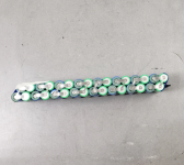
Life is good again.
Battery Clearing House has a deal on some Samsung 25R packs, 16S/2P, already welded glued and ready to solder into bigger packs.
Exactly what I need. So I hit the buy it now button on six packs, and hopefully I won't regret it.
Anyway, unless something goes wrong, I can whip up a 16S/12P pretty quick, and have that part of the equation taken care of soon.
It sorta sounds like these cells aren't in the greatest condition, but good enough for now, and if a few are duds then I'll still have a
big enough pack.
https://www.batteryclearinghouse.com/collections/18650-cells/products/samsung-25r-8s2p-25a-max-discharge-3-6v-2-5ah-18650-pack

Life is good again.
APL
100 kW
- Joined
- Aug 6, 2018
- Messages
- 1,113
Great day in the morning, batteries came today! Only took three days too! Now I get to see what kind of bad move I've made. 
They weren't kidding when they said the packs come apart easily, the glue doesn't stick very well. (The blue cells are double shrink wrapped, in case your wondering..)
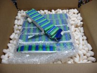
192 Samsung 25R cells came out to about $1.25 each, minus shipping. Boxed, taped, padded, and wrapped well,.. totally deluxe so far! :thumb:
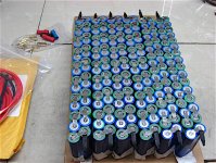
Not my favorite way to see a pack made, not for a bike anyway, but once I get the compression box tweaked, I can fill it with the Samsung's, and all will be well in the world.
The batteries look real good upon the first look, clean and fresh, and they all read the same 55.8v, so I'm getting more amazed.
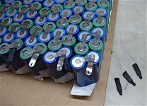
It gets better when I look closer,.. no power wires or connectors have ever been used, just heat shrink covers!
NOS cells, could I be that lucky? I fully expected far worse.
Edit;
Apparently so. But a look around the net at date codes brings up TJQ3 as a March 2019 cell,.. so a little long in the tooth to be sitting around on a shelf. Stored at the right volts and reading good though, so I have high hopes.
The plan is to Kapton tape the crap out of them, use the thin fiberglass sheets to separate, and make a quick heat shrink pack.
Probably just a 10P, since that will be plenty to light this controller up at 20A each. Then we will know for sure where the problem is.
They weren't kidding when they said the packs come apart easily, the glue doesn't stick very well. (The blue cells are double shrink wrapped, in case your wondering..)

192 Samsung 25R cells came out to about $1.25 each, minus shipping. Boxed, taped, padded, and wrapped well,.. totally deluxe so far! :thumb:

Not my favorite way to see a pack made, not for a bike anyway, but once I get the compression box tweaked, I can fill it with the Samsung's, and all will be well in the world.
The batteries look real good upon the first look, clean and fresh, and they all read the same 55.8v, so I'm getting more amazed.
It gets better when I look closer,.. no power wires or connectors have ever been used, just heat shrink covers!
NOS cells, could I be that lucky? I fully expected far worse.

Edit;
Apparently so. But a look around the net at date codes brings up TJQ3 as a March 2019 cell,.. so a little long in the tooth to be sitting around on a shelf. Stored at the right volts and reading good though, so I have high hopes.
The plan is to Kapton tape the crap out of them, use the thin fiberglass sheets to separate, and make a quick heat shrink pack.
Probably just a 10P, since that will be plenty to light this controller up at 20A each. Then we will know for sure where the problem is.
APL
100 kW
- Joined
- Aug 6, 2018
- Messages
- 1,113
Some progress,
Just a simple shrink pack using the glass board I had from the last packs I took apart. The 2P packs have fiberglass separators.
But I may need to use it for a while if the other battery has issues that take time. Only need about 6A a cell to check the controller, so it should do.
Found two slightly dented cells in one pack, so I removed them, and now it's a 10P pack with spare cells.
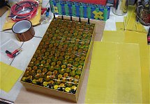
Black shrink wrap and XT connectors finally arrived, so now I can finish it up. One good thing is that I can use lots of foam rubber padding now because it's a lot smaller pack.
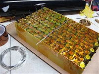
Already had some tinned copper strip, so I cut it in half for some thin flat P strips.
Lots of Kapton tape keeps me from the dreaded spark monster while I put it together,.. you know the one. :?
:?
Just a simple shrink pack using the glass board I had from the last packs I took apart. The 2P packs have fiberglass separators.
But I may need to use it for a while if the other battery has issues that take time. Only need about 6A a cell to check the controller, so it should do.
Found two slightly dented cells in one pack, so I removed them, and now it's a 10P pack with spare cells.

Black shrink wrap and XT connectors finally arrived, so now I can finish it up. One good thing is that I can use lots of foam rubber padding now because it's a lot smaller pack.

Already had some tinned copper strip, so I cut it in half for some thin flat P strips.
Lots of Kapton tape keeps me from the dreaded spark monster while I put it together,.. you know the one.
APL said:Lots of Kapton tape keeps me from the dreaded spark monster while I put it together,.. you know the one.:?
You mean the one that gave Plasmaboy his name? :lol:
https://web.archive.org/web/20071012140533/http://www.plasmaboyracing.com/blog/?page_id=10
So are all power tools. They exist so we can screw things up faster. 
APL
100 kW
- Joined
- Aug 6, 2018
- Messages
- 1,113
Finished up the temp pack, added some copper bus, soldered on dual 10g wire leads', and covered it with some more glass sheet.
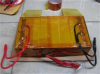
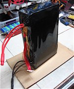
Shrink wrapped it, and the Monolith lives! Hungry for electrons. Not bad for the cost of shrink wrap and tape
So I put it in the bike, gave it a good charge and took it out for a spin and... . . same damn thing, twelve thirteen hundred watts. :lol: Crap! Still no victory ride.
But it's both good and bad news because it means that the batteries are good, and the pressure pack I made is working fine, so I don't have to eff with that, plus I have some nice Samsung's to fill it with that I needed anyway.
I also drained and measured all the individual cells in that pack and they all held the same volts, so it's kind of proof positive, pack was working fine.
Bad news is I'm back in the controller buying business, and I have to admit that everybody was right, and it is the controller.
Looks like they advertise 80A, but limit to 20A, or maybe they have little pee wee amps.
Might have to send off to China for the Votol, but I was also eyeballing used Sur Ron 60V units,.. cheap on the bay from people doing upgrades. Risky though, hmm, well back down controller road...
Cant think of anymore suspects except for the motor, and that runs like a top.
Damn! Your "temp" pack looks a lot more finished than a lot of peoples' perm. packs!APL said:Finished up the temp pack...
APL
100 kW
- Joined
- Aug 6, 2018
- Messages
- 1,113
Thanks 99t4, I like this pack,.. compact and light, I'd like to keep it. :thumb: But having non-parallel cell cans in contact with only thin wrap between them makes me cringe. My bike bounces around way to much for that.
I can trust it for a little while though.
I can trust it for a little while though.
APL
100 kW
- Joined
- Aug 6, 2018
- Messages
- 1,113
So I've made the decision to get the Votol EM-100, which I should have done in the first place, instead of wallowing around in Yantan
land. Oh well, we all know about that crap now, and at least all the wiring and mounting issues are a direct swap over.
Just working on some finance maneuvering,.. QS want's to use Western Union, and of course there's the shipping time, so it may be a little while. Bike is working pretty good now even with the underwhelming 1200w, and I'm still riding in the summer sun, so it's all good. :wink:
I'm still curious why the other controller(s) won't give the current they should.
My brain keeps wanting to analyze them, and look inside, poke around and do some testing.

:lol:
My brain keeps wanting to analyze them, and look inside, poke around
:lol:
APL
100 kW
- Joined
- Aug 6, 2018
- Messages
- 1,113
Me too. I could take it apart and poke around, but I need it right now and don't really know what I'm doing. Once I have another controller that works I'll be happy to send this one to you for an autopsy, if you're up for it, (don't need it back). If you can figure it out, then these controllers might be another cheap alternative.
I keep thinking that I must have something wrong, since the amps are so far off. The first thought was maybe the anti theft system connection's, but a low-output mode is no better than a no-output mode, and I don't see any other controllers with that kind of anti theft. (never connected that stuff up anyway)
The next thing is the throttle volts. The controller says 1.2v - 4.3v , but maybe the Crystalyte throttle is not a good match. Could the controller be not seeing enough throttle V? It does seem to have a kind of dead zone at first, but I can't be sure.
Then there's the LVC, but I'm giving it 54v to 67v and I have it on the 60v mode. I tried the 72v mode and it would barely move.
There's the Hall and phase wiring combinations,.. but I don't think it can be wired wrong and still run good. It either goes forward well, reverse well, or not at all, or with lots of noise. (Right?)
The other thought was to open it up and do the shunt solder thing, to try to get a little more out of it, I assume the limit function runs off the shunt. Unless you can think of something else.
Edit; This ad I found has a lot of internal pictures of the controller, including a mystery object, for what it's worth, .. page down a bit for photos.
https://alitools.io/en/showcase/sine-wave-controller-3000w-60v-72v-big-power-e-bike-brushless-motor-sensor-sinusoidal-wave-controller-1005001800418735
That might be a plan worth pursuing.APL said:Me too. I could take it apart and poke around, but I need it right now and don't really know what I'm doing. Once I have another controller that works I'll be happy to send this one to you for an autopsy, if you're up for it, (don't need it back). If you can figure it out, then these controllers might be another cheap alternative.
I'd have to look into that part; I don't know how it is intended to work.The first thought was maybe the anti theft system connection's, but a low-output mode is no better than a no-output mode, and I don't see any other controllers with that kind of anti theft. (never connected that stuff up anyway)
That can be tested with a voltmeter. If the throttle you have doesn't give enough voltage, you can use a potentiometer instead, just to test it.The next thing is the throttle volts. The controller says 1.2v - 4.3v , but maybe the Crystalyte throttle is not a good match. Could the controller be not seeing enough throttle V? It does seem to have a kind of dead zone at first, but I can't be sure.
If it is a torque-control system (vs speed control) Then not getting enough throttle would just mean less torque, which means less current draw from the battery as well.
As a side note, it wouldn't change the maximum speed...unless it takes that much torque to make it reach that speed.
It's possible that with the setup software and cable for it (if there is any available) that the throttle range could be altered to match whatever you've actually got (like the Cycle Analyst can do).
I doubt that's the problem; if it's on mode for a 60v battery it would have a likely lvc of 48-52v. at 60v+ it wouldn't ahve a reason to limit anything.Then there's the LVC, but I'm giving it 54v to 67v and I have it on the 60v mode. I tried the 72v mode and it would barely move.
Yes, or excess battery current (the opposite of what you're seeing).There's the Hall and phase wiring combinations,.. but I don't think it can be wired wrong and still run good. It either goes forward well, reverse well, or not at all, or with lots of noise. (Right?)
I wouldn't do that, just because it means the controller then can't know what the real current is, so if it's doing this limiting because it is trying to protect itself against some problem, it could just blow up.The other thought was to open it up and do the shunt solder thing, to try to get a little more out of it, I assume the limit function runs off the shunt. Unless you can think of something else.
Edit; This ad I found has a lot of internal pictures of the controller, including a mystery object, for what it's worth, .. page down a bit for photos.
https://alitools.io/en/showcase/sine-wave-controller-3000w-60v-72v-big-power-e-bike-brushless-motor-sensor-sinusoidal-wave-controller-1005001800418735
Looks nice enough inside...but:
Interestingly, this pic shows a transformer (probably for the LVPS SMPS circuit) actually broken off the board and sitting next to where it should be; the next one shows just that part by itself. Another pic of a different controller shows a large resistor with one lead broken off at it's base.
https://ae01.alicdn.com/kf/Ucdd287136de24cde95de2b204363fe26f.jpg_.webp
https://ae01.alicdn.com/kf/U4debb6d471c74401984e4734f79c1c1eK.jpg_.webp
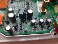
FWIW, the seller on the linked page (perfectly outdoor store) is one I've bought from once:
https://www.aliexpress.com/item/3256801614321326.html?spm=a2g0o.order_list.0.0.3a7c1802TXeiTv&gatewayAdapt=4itemAdapt
Looks like neither the linked controller nor the guitar effects thing I linked are available from them anymore, though.
https://www.aliexpress.com/item/3256801614103983.html
APL
100 kW
- Joined
- Aug 6, 2018
- Messages
- 1,113
Probably just what's wrong with mine,.. transformers snapped and the resistors clipped! :lol:
I was wondering what the transformer was.. or why would they even show it?
Working on how I'm going to check the throttle volt, probably fine, but should take a look, controller v and sensor v.
I was wondering what the transformer was.. or why would they even show it?
Working on how I'm going to check the throttle volt, probably fine, but should take a look, controller v and sensor v.
As I noted above, it's probably for the LVPS SMPS circuit (the low voltage power supply that creates the 5v, 12v, etc out of battery voltage--the broken resistor on a different controller is part of a similar circuit). Those are customer pics, so they're probably showing that it was damaged in shipping and found floating around in the case (probably rattled).APL said:Probably just what's wrong with mine,.. transformers snapped and the resistors clipped! :lol:
I was wondering what the transformer was.. or why would they even show it?
If yours was broken in either of those fashions, it would not turn on at all. (no power to run the brain, etc).
Based on the pics on that site, the only thing I can imagine that could be physically broken on yours to cause operation at too low a power is a current-monitoring circuit. This could be the actual current sensor, but is probably not--that would probably cause a complete failure to sense current at all, and/or even to power on and/or operate the motor (depending on sensor type). It would be more likely one of the amplifer circuits between the sensor and the MCU, like a wrong resistor soldered in, or one not soldered in at all, or some other "easy" mistake (but that is probably not visually obvious).
If you need to check the actual throttle output voltage, just connect it to the controller and use a voltmeter with black lead on battery negative / ground, and red lead on throttle signal wire. Alternately use a 5v source (USB port on any computer / USB charger etc) to power the throttle without connecting it to the controller; measure with meter at same wires.Working on how I'm going to check the throttle volt, probably fine, but should take a look, controller v and sensor v.
Make sure wheel is offground while testing the throttle if connected to controller, or engage the ebrake of the controller to disable it.
Using a potentiometer on the throttle input of the controller is a pretty easy way to check actual controller operation vs the throttle you have. You probably don't even have to order one, if you have any old speakers or radios laying around that you can cannibalize for parts--the volume control is usually a 10kohm potentiometer, and so is the balance control or tone control.
Similar threads
- Replies
- 6
- Views
- 1,037
- Replies
- 8
- Views
- 525
- Replies
- 45
- Views
- 3,801


![Samsung%20INR18650-25R%202500mAh%20(Green)%20Ebay-Capacity[1].png](/sphere/data/attachments/180/180962-3d287b2371f3ae0383e817ed822d3211.jpg)