Axiom: a 100kW+ motor controller

mxlemming said:
Arlo1 said:
Your light bulb analogy would be ok for single phase but the current has multiple phases it can travel though when talking about each switch.
No, it's exactly because there are 3 phase switching at the same time that this technique is so effective.
No that's what I am getting at they are not at the same time. All 6 switches are timed differently.
Arlo1 said:
What you need to show is 3 positive switches that and 3 negative switches that can turn off all effecting each of the 3 phases. This is why you need to talk about PWM frequency of each switch. The center aligned is nice and it can help a bit. But in all controllers I have worked with other than VESC stuff it talks about PWM frequency and if its center aligned it is better but its not truly 2x better as you would expect.
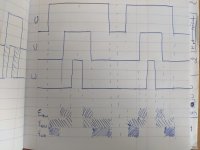
Yes it is literally 2x better. Considering 2 phase, in each pwm cycle with edge aligned you get 1 power and 2 freewheel states. With centre aligned you get 2 power and 2 freewheel. The kicker with the edge aligned is that there's a useless transition between two freewheel states which does nothing other than waste energy and heat your FETs/igbts. This reduces edge aligned to 1 power and one freewheel state.

In 3 phase this is 2 different power, 2 freewheel with edge aligned and 4 power 2 freewheel with center aligned.

[/quote]
This is incorrect and I have proven this in the past. You would think this is the same as 2x the PWM frequency in a edge aligned controller or a Top or Bottom only switched controller but its not.
I'm not saying its not the best way. I think its great but not exactly 2x as good.
To prove this I will need to dig back to testing I did 5-6 years ago. So Its likely something I will need to do new testing again.
 
Ok, i can see how at high duty cycles there tends towards a pulse-pulse..... pulse-pulse.... Behavior between phases but this is only between similarly low or similarly high duty/BEMF phases where the induced ripple will be lower. For the phases with larger BEMF difference, they remain equally spaced.

PXL_20210723_123217256.jpg

At low duty cycles, it will exactly equal 2x edge aligned, at high duty, the most ripple inducing voltages will remain well centered, and the lower BEMF phases will see distortion of the timing, so there is an effect but it's pretty small.

But as compared to the switching of the edge aligned and the dead time and misalignment of gate driver response times inducing error and the extra period of fast decay... You've got a different source of ripple and error but which is more significant I'm not yet sure.
 
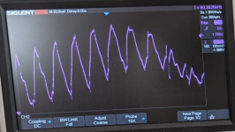
I just went and plugged a 1.5uH (one point five) motor into my MESC, and got this.
Current ripple 1.5uH motor, 15V, 12.5A per div.PNG
Was running at 15V, 35kHz centre aligned (70kHz switching).

The ripple current is enormous, you can see 4 divisions at 12.5A/div gives about 50A ripple, on a signal of only about 10A.

More than the ripple, the real problem is that controlling the current at this kind of inductance and ripple is virtually impossible.The exact point at which the ADC samples, what the other phases are doing etc... are all critical in determining the current measured, and so the noise that goes into the control loop is huge.

I honestly don't understand why people wind motors with such low inductance. Presumably it's something about getting high power density, but I have similar size motors with similar kV and power ratings that have an order of magnitude difference in inductance.
 
Shouldn't the reverse bias diodes being absorbing most of that?

My current understanding is that you want very low impedance if you are going for a high RPM motor. Or I guess you can have less poles. I am curious how the 20k+ Tesla motors are setup.
 
hallkbrdz said:
Shouldn't the reverse bias diodes being absorbing most of that?
No. This is normal, but a extreme case. The reverse bias diodes, if conducting, would result in even more current ripple since they only conduct to push current against the voltage gradient.
You can see the diode conduction just after each current peak, where the current drops very rapidly for a short period (the ~400ns dead time I am running).
hallkbrdz said:
My current understanding is that you want very low impedance if you are going for a high RPM motor. Or I guess you can have less poles. I am curious how the 20k+ Tesla motors are setup.
There's certainly a limit to the amount of inductance that you can have for a given rpm, but that's limited by the motor being unable to change current fast enough to track the sin wave (acting like a low pass filter)... clearly this, and the aforementioned QS205, are far far from that...

Inductance is a serious problem for stepper motors, but they are like 50+ pole pair. Typically when you hear of motors being inductance limited, they have mH of inductance, not uH.

I am also wondering what the Tesla motor parameters are like. A cursory google search found nothing.

I guess a few hundred uH inductance and virtually no mohms. From memory of the pics, they aren;t that many pole pair.
https://endless-sphere.com/forums/viewtopic.php?f=30&t=97880&start=50 Not the latest one, but there's a pic there of 6 pole pairs.
 
for your low inductance machine, upping the switching frequency is needed but you have to do more. you need a current sensor with a minimum 50kHz bandwidth preferably minimum 80kHz. the hardware signal conditioning circuit also must increased its cut-off frequency because you'll need the control loop to work on the switched current rather than the average current. the uC also has to be able to go through the loop with low delay.. group delay represents controller instability.

and finally, make sure your deadtime does not eat more than 5% of the switching period (which just got smaller but deadtime stayed the same).

when you've balanced the SYSTEM to work at a higher rate then you have a chance. now re-tune the PI current regulator and try again.
 
Hackey said:
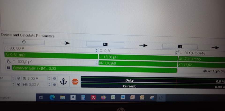
Hey Marcos, i recently sent that palta tech vesc to a friend in germany and he is using it with is 8kw qs mid motor. That motor is very low inductance like 10-15uh and throws abs overcurrent fault with overcurrent upto 1200amps( as seen on typing faults in terminal) is there any way we can run this motor.i am attaching detection results below.


30be77296d360007e9789d58b34aea3e.jpg


Sent from my Poco F1 using Tapatalk

Hi, I have one of those motors too.
Are you sure about those numbers for resistance and inductance?

I have a sevcon gen4 size6 I planned to run it with, do you (to all the knowledgeable people in this thread) think that will work?

Sorry for ot
 
mxlemming said:
I just went and plugged a 1.5uH (one point five) motor into my MESC, and got this.
Current ripple 1.5uH motor, 15V, 12.5A per div.PNG
Was running at 15V, 35kHz centre aligned (70kHz switching).

The ripple current is enormous, you can see 4 divisions at 12.5A/div gives about 50A ripple, on a signal of only about 10A.

More than the ripple, the real problem is that controlling the current at this kind of inductance and ripple is virtually impossible.The exact point at which the ADC samples, what the other phases are doing etc... are all critical in determining the current measured, and so the noise that goes into the control loop is huge.

I honestly don't understand why people wind motors with such low inductance. Presumably it's something about getting high power density, but I have similar size motors with similar kV and power ratings that have an order of magnitude difference in inductance.
You need to sample the ADCs not at the same rate as PWM, as aligning is too difficult. When an ADC samples you create aliasing where everything folds back into baseband (Nyquist theorm). You need to sample at a rate where PWM induced currents (which are at double the pwm frequency) fall close to or at fsample/2. This is what the recommendated sampling freq in the Lebowski controller is aimed at.

In laymans terms: if you sample at double the rate you dont need to aim for the midpoint of the ripple. The average of the two samples is the midpoint, independent of when the samples are taken (but the two samples must be equi-distant, which is easy)
 
Lebowski said:
You need to sample the ADCs not at the same rate as PWM, as aligning is too difficult. When an ADC samples you create aliasing where everything folds back into baseband (Nyquist theorm). You need to sample at a rate where PWM induced currents (which are at double the pwm frequency) fall close to or at fsample/2. This is what the recommendated sampling freq in the Lebowski controller is aimed at.

In laymans terms: if you sample at double the rate you dont need to aim for the midpoint of the ripple. The average of the two samples is the midpoint, independent of when the samples are taken (but the two samples must be equi-distant, which is easy)

Glad you're back!

Interesting idea on the pwm vs sampling frequency. Makes perfect sense, but I don't think I can implement this on my MESC controller since I'm not using phase shunts.

I'm coming round to the idea that phase shunts might be worth the extra electronics hassle.

You say aligning is difficult... On the stm32 on my controller and VESC, the ADC is triggered by the timer so the acquisition time is essentially perfectly aligned in time with pwm... But I assume you are well up to speed with that so are you referring to something else, like the eventual symmetry of the waves as a result of the 3 phases pwms varying and making the irregular shapes?

How about the PID gains on the current controllers? VESC calculates fairly aggressive gains based on the proportional voltage given the phase inductance resulting in a current change to the required within 1pwm cycle. My inclination is that this is far too aggressive for an ultra low inductance motor. Any advice on how to set this? I recently implemented the same strategy, where previously I'd been hard coding comparatively low gains and found this was incredibly jittery by comparison.
 
Gearing up for some stress test.. +200kW? We’ll see! :)
 
HighHopes said:
Gearing up for some stress test.. +200kW? We’ll see! :)

Fingers crossed for you guys making it to 200kW! Thats big HP from a tiny controller! :bigthumb: :bolt: 8) :mrgreen:
 
Putting a video together 200kw peak should be a walk in the park with good cooling

New Axiom record!.JPG
 
A much overdue update about Axiom. We have been running tests and working on things like the enclosure. But today we went to what would likely be full voltage! I apploagize for the unedited video but working is more important then editing videos at this point! Stay tuned as 200kw peak should be on the table! [youtube]sUCmC9pwhS4[/youtube]
 
I already commented on the YT video, but great work! Can't wait for this to hit production. If this end up being able to clear 200kW peak, I'm for sure on board to buy one!
 
nismoman240sx said:
I already commented on the YT video, but great work! Can't wait for this to hit production. If this end up being able to clear 200kW peak, I'm for sure on board to buy one!

Its important to note this is stress testing and we will likely limit the peak power a little lower.
But we have plans to offer a higher power version as well for a little more money.
 
If it's it's even remotely less than the $15k that Cascadia Motion wants for a CM200, I'll be happy. Plus that CM200 will take them programming it to get it to work with a Leaf motor... = More $
 
nismoman240sx said:
If it's it's even remotely less than the $15k that Cascadia Motion wants for a CM200, I'll be happy. Plus that CM200 will take them programming it to get it to work with a Leaf motor... = More $

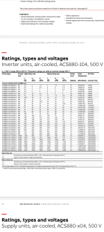
For 15k you could have an ABB ACS880 200kW drive that will push that much power all day... And has safety features, UL approval and DTC, will run just about any motor... And can be bought right now off the shelf.

15k is a shit load of money. You can get a lot of inverter drive for 15k.
 
I hadn't heard of that one before, but you totally see my point. $15k for an inverter seems crazy to me if you only need 200kW for around 10 seconds (drag strip).
 
Likely Axiom will be $6500 USD and the version with more power will be $8500 USD

-Arlin
 
For 15k you could have an ABB ACS880 200kW drive that will push that much power all day...

it also weighs over 200lbs and is huge. also its performance specs are less. and is more than double the price. its not apples to apples comparison, its applesto a freak'n lemon
 
HighHopes said:
For 15k you could have an ABB ACS880 200kW drive that will push that much power all day...

it also weighs over 200lbs and is huge. also its performance specs are less. and is more than double the price. its not apples to apples comparison, its applesto a freak'n lemon

6500 is a sensible price. Makes sense, reasonable given it's a build of a nominally open source design, ~half the acs880 etc.

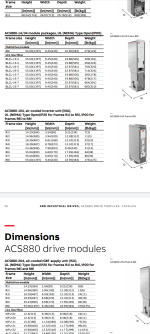
Not sure where you're getting 200lbs, the manual I found said 38kg for R6i and R7i case option acs880-104 air cooled which iirc run up to 200kW and is the option that runs from dc bus (correct me if I'm wrong, the options and combos are a mine field), though working out which is the comparable spec option is tricky, plus I'm not sure how it compares to the axiom once you add the 2000W of cooling you'll need at 99% efficiency 200kW continuous and the box to hide the 400V and so on.

The 200lb r9 and r8i (276lb) go up much higher to a claimed 500kW continuous, 600kW for 1 minute out of every 5. That's a very big inverter.

Pricing wise, I'm taking a best guess based on pricing i found online for claimed new 120kW continuous units. If I'm wildly out on pricing, sincere apologies please correct me, i haven't tried actually buying these units.

Could you comment on ABB's direct torque control and power speccing? Genuinely really interested. Is it just outright lies/works poorly/..? It's a big claim that the Axiom is an apple to ABB's lemon. ABB seem to be of the impression that their controllers and software are the best and I've certainly seen a lot of them around factories, ships, buses, trains etc.

I've worked for a few megacorps, and while I'm well aware they're slow, inefficient,tedious... Have larger marketing budgets and present rosie images, one other thing that's true is that everyone flips their nut when specs aren't met and aren't justifiable, and they flip their nut even harder when things aren't safe, don't convincingly pass every standard claimed etc.

Except Volkswagen and a few others apparently.
 

Attachments

  • Screenshot_20210823-005032.png
    Screenshot_20210823-005032.png
    146.1 KB · Views: 1,416
  • Screenshot_20210823-004809.png
    Screenshot_20210823-004809.png
    141.4 KB · Views: 1,416
Broke 200kw peak. More to come!

-Arlin

[youtube]aXj-5bpwK00[/youtube]
 
SlowCo said:
nismoman240sx said:
I'd buy it right now for those prices!

What will you use it for? What kind of build (vehicle/motor/battery type) will it go into?
I have a Nissan 240sx that has a turbo 1.8L that makes over 400whp on E85. It's been fun building it and playing with it for the last 20 years, but I'm ready for something new and different. I recently bought a 2015 Leaf and I've been bitten by the EV bug and want to convert it. I'm used to the performance it has now, but it's also nearly unusable on the street due to how much power it makes. I was already thinking about putting a smaller turbo on it to pull the power back down to 300whp. Now that I have an understanding of how different power is delivered with an electric motor, I think low-mid 200hp will satisfy me enough to still enjoy the car, but not be incredibly difficult/expensive to build.
 
Back
Top