Battery issue - iZip E3 Dash

rick_p

100 W
Joined
Feb 16, 2021
Messages
260
Location
Los Angeles
Hello,

I picked up a used, non-operational iZip E3 Dash, the price and the challenge to get it back on the road were too great to resist :wink:

I have been down this road before, and thanks to all the amazing advice, tips and tricks I have received on this forum in the past, I at least knew where to start with troubleshooting.

The symptom; the dreaded blinking red light on the charger, so I knew right away that aside from anything else that might be wrong, there's either a battery or charger problem.

What I have tried/checked so far:
  • With battery off the bike and no charger, there is zero voltage at the charge and discharge ports, and obviously no lights at charge level indicator on the battery.
  • I attempted to test the output voltage of factory charger, but I think this charger is one that doesn't put out any voltage until there is a load. The charger has a green light before plugging it into the battery, it blinks red when plugged into the battery, and there is zero voltage at the discharge port with the charger left plugged in.
  • I tried a known working charger with the same specifications and plug type. When I plugged this charger in, the light stayed green on the charger instead of changing to amber and the fan turning on as it normally does when it's charging a battery. There was 54 volts at the discharge port with the charger plugged in.
  • I tried a soft reset on the BMS by charging the battery for a only a minute via the discharge port, but no luck there, it still doesn't charge.
  • I opened the battery case and everything looks new inside, there's no indication of any short circuits or water damage or anything like that. Due to the (clear) shrink wrap I wasn't able to get to the BMS yet to try a hard reset, and this is where I stopped.

An interesting note to add, and one of the reasons I decided to post this is, after I did the previous tests and attempts to reset the BMS, I got a very low but negative reading at the discharge port. For a second I thought maybe I attached the charger to the discharge port with the polarity reversed, but then I remembered that I checked the voltage during the one minute the charger was attached to make sure it was getting a charge, and it was connected correctly.

Any and all ideas and advice is much appreciated. I have reason to believe this bike has low mileage, so this battery is probably worth trying to fix.
 
rick_p said:
This is really cool, I wonder if I’d be able to figure out the wiring given the current controller is inside the hub motor. I guess the best way to do it would be to eliminate that controller and install an external one, but that would require cutting the cable to the hub motor and figuring out which wires are the hall wires, the power wires will be obvious, but there are probably more wires than a typical hub motor cable.
For controllers actually inside the hub, to replace with external you'd have to ditch the existing motor cabling (taht goes from inside the motor to outside) and replace with a new one. Simplest is a sensorless controller, so you only have to run the three thick phase wires out, but they may not startup from a stop as well as sensored controllers that do use the hall wires, if you're not pedalling and only using throttle. If you pedal to startup you're already getting it moving yourself so it would likely startup just fine sensorless.

I used full sensored recabling for an Ultramotor (previously internally controlled) here:
https://endless-sphere.com/forums/viewtopic.php?f=2&t=86600&p=1608835&hilit=ultramotor+stromer#p1463762
if yours is similar the same basic procedure would work. If the replacement controller has "self learn" then it simplifies figuring out the phase/hall wiring combination (which probably wouldn't be the same between it and the internal controller).

I used the buy-by-the-meter cable Grin Tech sells, because I wanted to put as large a phase wires as I could into it while sitll using an integrated single pre-existing cable. If you don't need more than "basic" power (whatever it was originally designed with) you could even buy one of those "bafang" julet/higo 9-pin motor cable extensions, cut it in half, and use half for the motor rewring and half to put on the controller (if it doesn't already come with this connector; some do).

I have a thread here showing this on a Dapu motor that just needed a new cable due to wire damage:
https://endless-sphere.com/forums/viewtopic.php?f=30&t=114480


BTW, if there is room inside the motor, you might be able to fit the Baserunner, or perhaps the Frankenrunner / Phaserunner from Grin Tech in there in place of the old controller. Something to look into...but the BR/FR/PR are a lot more expensive than a generic dumb controller (which would probably work fine externally) and you'd still need the CAv3 to get the PAS sensor stuff. (if you didn't need any PAS stuff you could use whatever controller did the other stuff you wanted, internal or external, and not worry about the CA..but to get tunable PAS it's the only thing I know of like it out there).
 
amberwolf said:
For controllers actually inside the hub, to replace with external you'd have to ditch the existing motor cabling (taht goes from inside the motor to outside) and replace with a new one.

Thanks for the great information and the links to your posts showing how to make a controller conversion!

I went through all the wiring on the bike, and man there’s a lot of it. I checked every connector, and cleaned all exposed items like the throttle and brake sensors. In addition, I found a review that answered all my questions about torque and PAS sensors, and yeah, it has a torque sensor. It turns out that I was wrong about the throttle though, it does support TAG, and it even supports it while in PAS mode. After the cleaning I took it out for a longer ride and although it does take a little getting used to the sensors constantly adjusting the speed and power according to peddle torque and cadence, I think I can get used to it. In fact, this thing is faster than my other bike, and not by just a little, and the throttle is working like it’s supposed to now. So yeah, I think I’ll leave well enough alone. But I will keep adding to this post so that others who pick one of these up will have as much information as possible to restore theirs.

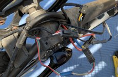
For example, if you have one of theses bikes or one like it, there is a rubber boot next to the bottom bracket with all these connectors crammed inside the frame. The boot on mine was dried out and cracking, so I pulled out all the connectors as you can see below and made sure none had gotten wet, which surprisingly they had not, but I opened and reconnected all of them just to make sure they were clean and getting a good connection. It was challenging to get them all tucked back inside, and I definitely don’t trust this boot for water tightness, even if I had a brand new one, it’s just a crazy design, so I plan to redo this later and will post how I accomplish it.
CB721B8E-9A7F-42A2-8642-1251080595A8.jpeg
 
I have discovered thru experience and forum posts that waterproofing *anything* to keep water *completely out* is nearly impossible to achieve.

What it usually ends up doing is keeping most of what water does get in, in. :(

So, unless you ride where the areas in question are likely to get actually submerged, I'd recommend making something that sheds water from the areas, keeping as much as possible from getting in there, but also has at least one drain hole at the very lowest point when the bike is sitting in whatever it's parked position is. Each drain hole has to be large enough that it is bigger than water's surface-tension-flow-resistant-area. I don't know what the proper term is, but basicallly if you have a hole small enough, water under insufficient pressure will not flow thru it, it will just hang there in it, and all that will happen is that what little surface area there is exposed to the outside will eventually allow it to evaporate away...but it can do damage in the meantime if it's on corrodeable surfaces.

You can also pack all connectors, both where they mate and where wires enter, with dielectric grease (like the stuff for battery posts at auto places). That will keep water out of them, at least.

The hotglue (or silicone) it looks like they used to fill the backs of those connectors is not waterproof, because over time it separates from the plastic housing, and water is VERY GOOD at sneaking between surfaces like that, and once inside, it gets all comfy and snuggly with the stuff it isn't supposed to, and they have little rust babies. :(
 
amberwolf said:
I have discovered thru experience and forum posts that waterproofing *anything* to keep water *completely out* is nearly impossible to achieve.

What it usually ends up doing is keeping most of what water does get in, in. :(

You can also pack all connectors, both where they mate and where wires enter, with dielectric grease (like the stuff for battery posts at auto places). That will keep water out of them, at least.
If that is the case (complete water proofing is nearly impossible) then what I’ll do is repair the existing rubber boot by spreading in thin layer of silicone over the areas that are cracking and call it done, because the way it’s designed, it already prevents spray coming off the front tire from dousing the connectors, and if any water did get in, it will drain because the hole where the wires come out of the boot is the at lowest point, and large enough for water to exit.

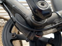
What I already did was rerouted the brake and gear cables to make some room in there. As much as I like through the frame cabling, it isn’t worth the reduction of space, access and serviceability of the electrical wiring to have those two cables in there. Removing those two cables made a world of difference, not only do the connectors fit in there nicely now, it makes the removal and installation of the boot way easier. Here’s the finished product…

93681B6F-0030-45A7-ACF3-5DEB357559CA.jpeg
 
I spent some time searching for information on the Tranzx torque sensor bottom bracket. I wasn’t able to find much at all about this specific sensor but found this article at Grin Technologies that covers several other brands. https://ebikes.ca/getting-started/pas-options.html

I have zero previous experience with torque sensors before picking up this bike, and while I don’t hate it, I don’t love it either. I don’t want to go as far as replacing it with a different type of sensor, but from the article I learned that most of these bottom bracket sensors detect cadence and torque, so I’m wondering if it’s possible to disable the torque sensor and just use the cadence sensor. Ideally, once the cadence sensor kicks in, the torque sensor would be at full torque.

As you can see in the pictures, the torque sensor has four wires, I’m wondering if anyone knows where I might find info on which wires carrying which signals to the circuitry that interprets the state of torque?
 
If you measure voltage from each pin to ground, you'll probably find one that is ground (0v), one that is power supply (5v to 12v+), one that is a variable voltage depending on force applied to the pedals (torque sensor), and one that is pulses (probalby 0v to 5v and back) as you rotate the pedals (cadence sensor).

As long as the bike's controller does not require reading the torque sensor to operate, you could just disconnect the variable-voltage wire.

However, there's a high likelihood that the controller will fault and not operate if it doesn't detect *a* voltage on that pin. You may have to put a voltage divider in that provides the nominal startup/static voltage out of that sensor to the controller, while the sensor itself is disconnected. It's simple, just two resistors, if you do need to do it.

Note that doing things this way will mean teh bike detects *no* torque at all, so if part of it's power-application is determined by that, you'd need to setup the voltage divider to provide the same voltage as the *maximum* voltage your voltmeter reads out of the torque sensor at maximum torque. If the controller is setup to error out if it detects max torque at power-on (which will happen with this method), then you'll need to put a switch in there that switches between the minimum and maximum levels. Or a potentiometer that lets you manually vary the level.


THere are also torque sensors that use a serial data connection for all info from them to the controller (one version of TDCM, for instance), and if that's the case here you'd have to decode what that data is, and make some sort of MCU device (arduino, etc) that filters the torque signal part to either alter it to react the way you like, or just not present it to the controller at all, while still providing it the cadence data.
 
amberwolf said:
If you measure voltage from each pin to ground, you'll probably find one that is ground (0v), one that is power supply (5v to 12v+), one that is a variable voltage depending on force applied to the pedals (torque sensor), and one that is pulses (probalby 0v to 5v and back) as you rotate the pedals (cadence sensor).

It took a month or more but I finally got around to this. Part of the delay was I would have had to remove the water proofing off of my connector to perform the test on my working bike, so I waited to do the test on a non-working bike sitting at the shop where I bought mine. Using my good battery, here are the readings from the bottom bracket torque sensor:

Red: power - 5 volts
Black: ground - 0 volts
Gray: cadence - 3.43/0 volts
Green: torque - 2.6 volts

I couldn’t find a technical paper for this sensor but I read the one for the TDCM sensor you mentioned and the voltages I got are somewhat consistent with the TDCM one. Interestingly though, the voltage dropped when I applied pressure to the crank, but I think it’s supposed to increase. Maybe that’s why this bike is inoperable.

Side note to all of this is I found technical documentation for the E3 Dash bike, and in those docs I found that the bike’s electronics have on-board diagnostics. My bike, which is operable checks out perfectly, all readings are within the required ranges. The not-operable bike fails one diagnostic, the start-up value for the torque sensor is way off the required range, but after turning the crank a few times it does come into specs, so I’m not sure why this bike never gets power to the wheel, and the wheel is tested good. Maybe once it fails startup it doesn’t reset until next startup.

I didn’t try removing the single torque wire because it seemed obvious to me that doing so would only cause it to fail startup like you mentioned. I also didn’t try any of the methods you mentioned to trick it into thinking the sensor is operating properly, I don’t have the materials on hand to do that.

On this non-working bike, I think it would be worth attempting to abandon the bikes original electronics and switch to an external controller, but going back to an earlier post, you mentioned…

“For controllers actually inside the hub, to replace with external you'd have to ditch the existing motor cabling (that goes from inside the motor to outside) and replace with a new one.”

I don’t understand this, why can’t I use the original cable exiting the wheel but only connect the power and phase wires and abandon the controller wires? With that question asked though, the connector has two large pins, and six small ones, the two large pins are obliviously the power wires, but I’m not sure how one would figure out which ones are the phase wires.
 
I'll reply to the other part later, but first:

rick_p said:
On this non-working bike, I think it would be worth attempting to abandon the bikes original electronics and switch to an external controller, but going back to an earlier post, you mentioned…

“For controllers actually inside the hub, to replace with external you'd have to ditch the existing motor cabling (that goes from inside the motor to outside) and replace with a new one.”

I don’t understand this, why can’t I use the original cable exiting the wheel but only connect the power and phase wires and abandon the controller wires? With that question asked though, the connector has two large pins, and six small ones, the two large pins are obliviously the power wires, but I’m not sure how one would figure out which ones are the phase wires.

Because a motor with internal controller doesnt' have any phase wires going to the outside for you to connect to. (they're only inside the hub, from the windings directly to the internal controller--see my Stromer Mountain33 motor thread for pics of how that one looks for an example).

You have to install phase wires from the inside to the outside, and there is almost certainly not enough room to do so without removing some of the other wiring. In addition, trying to run new wires thru the axle while leaving the old wiring in there, even if there's a bit of room, is probably far harder than replacing the entire wiring cable with a new one designed to be used with an external controller.

Theoretically you could use the two main battery power wires to the internal controller for two phase wires, and install just another matching guage wire for the third phase, but as noted, getting that thru there while the other wires are still there might not be possible (probably pretty difficult even if it's possible).

You might be able to pull the whole old cable out, and then reinstall it at the same time as inserting the new single wire (or set of three phase wires in the unlikely event there's room for them), but if you have to pull the old one out anyway, you might as well use a new one with the right wire sizes and number of wires to simplify the process. :)


If the motor has hall sensors, there will be another 5 wires (thin, though, rather than thick like the phases) needed to go from the inside of the motor to the outside, unless you're using a sensorless controller.
 
amberwolf said:
Because a motor with internal controller doesnt' have any phase wires going to the outside for you to connect to. (they're only inside the hub, from the windings directly to the internal controller--see my Stromer Mountain33 motor thread for pics of how that one looks for an example).

You have to install phase wires from the inside to the outside, and there is almost certainly not enough room to do so without removing some of the other wiring. In addition, trying to run new wires thru the axle while leaving the old wiring in there, even if there's a bit of room, is probably far harder than replacing the entire wiring cable with a new one designed to be used with an external controller.

Ah, I see the big picture now, and it changes how I feel about abandoning the original electronics. My thought was it might be worth spending a little money on a controller if that would get the bike back on the road a little faster, but it’s clear now that making this conversation will not save time. Now I’m thinking the fastest route would be to replace the torque sensor, even though it costs more than a controller.

Suddenly, taking a stab at tricking the controller into thinking the sensor is operating within specs as you outlined earlier seems more appealing, but it also sounds a little tricky to accomplish.
 
amberwolf said:
There's a high likelihood that the controller will fault and not operate if it doesn't detect *a* voltage on that pin. You may have to put a voltage divider in that provides the nominal startup/static voltage out of that sensor to the controller, while the sensor itself is disconnected. It's simple, just two resistors, if you do need to do it.

Doing things this way will mean the bike detects *no* torque at all, so if part of it's power-application is determined by that, you'd need to setup the voltage divider to provide the same voltage as the *maximum* voltage your voltmeter reads out of the torque sensor at maximum torque. If the controller is setup to error out if it detects max torque at power-on (which will happen with this method), then you'll need to put a switch in there that switches between the minimum and maximum levels. Or a potentiometer that lets you manually vary the level.

Let's assume everything you said is fact, because it probably is. Let's also make sure I understand how to set this up. If by chance you know of a post or other tutorial that covers this, I'm sure that will save us both time.

Unfortunately, I don't really understand this statement, largely because of my lack of knowledge of basic electronics, but if you point me in the right direction, I'm sure I can figure it out.
amberwolf said:
Put a voltage divider in that provides the nominal startup/static voltage out of that sensor to the controller, while the sensor itself is disconnected. It's simple, just two resistors, if you do need to do it.
If I have to go that route, specifications for the resisters and a wiring diagram will be very helpful.

A couple of thoughts that come to mind here, one thought is that the nominal startup/static voltage coming out of the sensor may already be in range (Green: torque - 2.6 volts). I hate to remove the waterproofing on my working bike, but if I do that I can verify a voltage that is in range for sure. The other thought is, there is an unused accessory light wire available, I can check how many volts are on that wire to see if that can be used to supply the nominal startup/static voltage to the controller instead of using what is coming out of the sensor.

One of those two methods would cover the nominal startup/static voltage, now comes the fun part, emulating the variable torque voltage(s) to trick the controller into providing full power. You mentioned...
amberwolf said:
Place a switch in there that switches between the minimum and maximum levels. Or a potentiometer that lets you manually vary the level.
Adding this to the wiring diagram will be very helpful. A switch is obviously easier because I can get one of those at the auto parts store, a potentiometer on the other hand sounds way better because it will be a much smoother power transition, but it may or may not be easy to come up with. For starters, I'm not sure what can work as a potentiometer or if it has to be a very specific thing, and it wouldn't be very safe if it wasn't something I could adjust without taking my (left) hand completely off the grip. Some guidance here will be helpful.

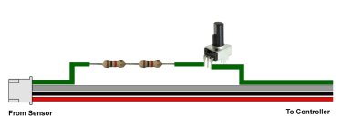
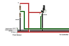
Something like this?
sensor-wiring-diagram.jpg
 
rick_p said:
Let's assume everything you said is fact, because it probably is.
It's deductions based on how similar systems are known to operate, rather than certainty--that will require testing. ;)


Let's also make sure I understand how to set this up. If by chance you know of a post or other tutorial that covers this, I'm sure that will save us both time.
Nothing with this system; and nothing with diagrams I can think of. There are sites like AllAboutElectronics.com that have tutorials / etc for probably any basic electronics concept / circuit / function, if you want to learn how various things work, but for this situation it's probably "TMI". ;)


Unfortunately, I don't really understand this statement, largely because of my lack of knowledge of basic electronics, but if you point me in the right direction, I'm sure I can figure it out.
amberwolf said:
Put a voltage divider in that provides the nominal startup/static voltage out of that sensor to the controller, while the sensor itself is disconnected. It's simple, just two resistors, if you do need to do it.
If I have to go that route, specifications for the resisters and a wiring diagram will be very helpful.

Actual resistor values don't make too much difference, other than that you'd need to experimentally determine the specific fixed voltage you want there, then calculate a ratio between that voltage and the supply voltage to the sensor. Then multiply that ratio to a resistance, like say, 10kohm, and you get two resistance values, one for the top and one for the bottom, wired up like in the diagram I included in this post.

Most of the time resistors for voltage dividers are used such that there is not much current flow thru them (to not waste power and generate heat) but so that there is *enough* current flow to be give stable output voltage against electrical noise in the system. For 5v systems, 5kohm to 10kohm is pretty common, for the total divider resistance.

Most resistors have a fairly wide (a few percent) tolerance, or variation in value allowed, so they're not "exactly" the resistance they say they are. If precision is required, there are precision resistors but they cost more. For a voltage divider, a potentiometer is often cheaper in this case.

For resistor wattage rating, even 1/8w is bigger than needed, but those are teh smallest non-surface-mount parts I know of. I usually use 1/4w solely because my fingers can handle them fairly easily. :)


A couple of thoughts that come to mind here, one thought is that the nominal startup/static voltage coming out of the sensor may already be in range (Green: torque - 2.6 volts). I hate to remove the waterproofing on my working bike, but if I do that I can verify a voltage that is in range for sure. The other thought is, there is an unused accessory light wire available, I can check how many volts are on that wire to see if that can be used to supply the nominal startup/static voltage to the controller instead of using what is coming out of the sensor.

If you use a potentiometer as the divider, you don't need to check the value, just set the potentiometer to the middle, then power on the system and then adjust it and observe the system reaction, making notes as you go. (with wheel offground ;) ). It's likely that you'll need to manually turn the pedals to get any system reaction; the cadence probably activates it while the torque signal tells it how much power to use.

WHen the system won't react at all to the pedals, you've probably got the static / poweron value.

One of those two methods would cover the nominal startup/static voltage, now comes the fun part, emulating the variable torque voltage(s) to trick the controller into providing full power. You mentioned...
amberwolf said:
Place a switch in there that switches between the minimum and maximum levels. Or a potentiometer that lets you manually vary the level.
Adding this to the wiring diagram will be very helpful. A switch is obviously easier because I can get one of those at the auto parts store, a potentiometer on the other hand sounds way better because it will be a much smoother power transition, but it may or may not be easy to come up with.

I didn't include switch in the diagram yet because it depends on how the systme works, and what you want the switch to do, for how it would be wired.

For a handlebar mountable switch, you can probably use the 3-speed switch or turn signal switch for ebikes. Or the Grin Tech 3 position switch (which comes prewired with specific resistors but you can take it apart and change them if you needed to).
https://ebikes.ca/shop/electric-bicycle-parts/ca-accessories/aux-input/ca3-switch.html


For starters, I'm not sure what can work as a potentiometer or if it has to be a very specific thing, and it wouldn't be very safe if it wasn't something I could adjust without taking my (left) hand completely off the grip. Some guidance here will be helpful.
Any potentiometer that physically works for you will work. Grin Tech sells one with a handlebar mount that's designed for the Cycle Analyst aux input:
https://ebikes.ca/ca3-aux-al.html
but you could even take a volume / balance / tone control pot out of some old speakers or radio and use that, if it works for you. I'd do your experimentation first with just some generic pot like that, before spending money on a permanent solution (in case the system doesn't work like others and this bypass won't work).


Now, the diagram: I drew in both the divider *and* the pot, but you only use *one* of these, not both at the same time. So you choose which one to use, and wire it that way. Call the top resistor R1 and the bottom R2, for reference if we end up discussing their values.
sensor-wiring-diagram.jpg
 
amberwolf said:
It's deductions based on how similar systems are known to operate, rather than certainty--that will require testing. ;)
If I’m understanding this correctly, which I’m pretty sure I am, not a lot of testing is required, and what testing is required will be easy, based on this next comment.
amberwolf said:
If you use a potentiometer as the divider, you don't need to check the value, just set the potentiometer to the middle, then power on the system and then adjust it and observe the system reaction, making notes as you go. When the system won't react at all to the pedals, you've probably got the static / poweron value.
Oh wow, this is so much less complicated than I imagined, I didn’t realize you can just turn up the potentiometer to get the right start up voltage, I was thinking you had to get the start up voltage correct separately, and then use the potentiometer to emulate the variable torque voltage. The onboard system diagnostics will tell me when the potentiometer is set to the acceptable voltage.
amberwolf said:
Any potentiometer that physically works for you will work. I'd do your experimentation first with just some generic pot like that, before spending money on a permanent solution (in case the system doesn't work like others and this bypass won't work).
Yes, very smart, and I’m sure I can find something.
amberwolf said:
Now, the diagram: I drew in both the divider *and* the pot, but you only use *one* of these, not both at the same time. So you choose which one to use, and wire it that way. Call the top resistor R1 and the bottom R2, for reference if we end up discussing their values.
sensor-wiring-diagram.jpg
I’m definitely going with the potentiometer, it’s way less complicated. I’m sorry you had to write up all that information about the resistors, but maybe it will be useful for others.

I should be able to make time for this today, I’ll post a follow up with pictures when I do. Hopefully I won’t have any questions before I can move forward.
 
rick_p said:
Oh wow, this is so much less complicated than I imagined, I didn’t realize you can just turn up the potentiometer to get the right start up voltage, I was thinking you had to get the start up voltage correct separately, and then use the potentiometer to emulate the variable torque voltage. The onboard system diagnostics will tell me when the potentiometer is set to the acceptable voltage.
after it's setup, just put a mark on the pot's mounting where it gives that startup voltage, for quick resetting. ;)


Note that it could still be useful to have the divider *and* the pot, and a switch between the two, if there is a common amount of assist you use, so you can leave the pot set to that but then just "turn it off" by flipping the switch to the startup divider, and turn it back on right to the level it was before.

You can also use a multi-position switch to switch between several dividers with preset levels.
 
amberwolf said:
After it's setup, just put a mark on the pot's mounting where it gives that startup voltage, for quick resetting.

You read my mind. In fact, if I get this to work, I was thinking of ways to fabricate a “stop” so I wouldn’t have to look at it every time I come to a light. One thought was to use a sliding potentiometer and simply glue a piece of plastic on the slide to stop it at the precise location. Then mount it within thumb’s reach on the left side.

I thought I had an old non-working stereo in the garage, but I guess I sent it to e-waste already. Finding a potentiometer around the house wasn’t as easy as I thought it would be, but I’ll find one.
 
amberwolf said:
Any potentiometer that physically works for you will work.

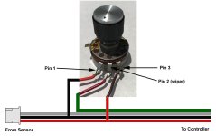
I found a potentiometer in an old attenuator I had stashed away. When I tested the pins using your diagram I found Pin 2 (middle pin) is in fact the "wiper" pin that fluctuates the current as the knob is turned.

When I tested the potentiometer using Ohms, the Ohms went up as I turned the knob clockwise. However, I also tested using a AA battery, and when I placed Pin 1 on the positive side of the battery, and Pin 3 on the negative side of the battery, which I think follows your diagram, the current started at 1.5 volts and went down as I turned the knob clockwise. When I reversed Pins 1 and 3 on the battery (Pin 1 negative and pin 3 positive) the current on Pin 2 increased as I turned the knob clockwise. Given this information, does this wiring diagram look correct to you?

potentiometer-wiring.jpg
 
Yes; it doesn't matter which outer leg you use for ground or positive, except for which direction you want to turn the knob to increase the voltage output (not current ;) ).
 
amberwolf said:
Yes; it doesn't matter which outer leg you use for ground or positive, except for which direction you want to turn the knob to increase the voltage output (not current ;) ).

Well, unfortunately it didn't work. The very first time I turned the bike on I had the potentiometer set at half way, and when I went into the diagnostics the "Factory Torque Value" was too low, it was 140 and the acceptable range is 520-570, and turning the knob did nothing because it probably only takes one reading at startup.

So, I turned the bike off and cranked up the knob to about 3/4 or a little more, then I turned the bike on, went into the diagnostics, and found the value had dropped to 007. My thought was "Oh, it's wired backwards, turning the knob clockwise actually lowered the voltage."

So, I turned the bike off and set the knob at 1/4 or less, then I turned the bike on and went into the diagnostics, but the value was still at 007. :?

Another diagnostic available is the "Actual Torque Value," which should start out at the exact same range as the Factory Torque value, and increases when pressure is applied to the pedals. That was low at first but it did respond to turning the knob on the potentiometer, it increased as I turned the knob clockwise so I set it to 540, which was about 3/4 of the knob's range, and then I turned the bike off hoping that would be the "Factory Torque Value" setting. I turned the bike back on, went into diagnostics and the Factory Torque Value was still at 007 and the Actual Torque Value was still at 540. :confused:

Now I was totally perplexed, so I turned the bike off and swapped the green (torque) wire coming from the potentiomter with the green wire coming from the bottom bracket torque sensor, but when I turned the bike on and went into the diagnostics, the Factory Torque Value was still at 007, and the Actual Torque Value was still at 540. :shock:

It was getting late so I gave up for the night, but to be honest, I don't know where to go from here. I'm no longer sure the problem is even the torque sensor.
 
Just a quick follow up to say that I double checked all my connections, disconnected the battery, reconnected, restarted diagnostics, and I can no longer get any reading other than 007 from the Factory Torque Sensor, with or without the potentiometer in the mix. Maybe I inadvertently changed something, or maybe there is some other problem.

This only started happening since I tried adding a potentiometer, but that certainly doesn't mean that is the cause of this behavior. In fact, I found an old post on another forum where someone else reported getting a 007 from this diagnostic, and in that case, the bottom bracket (sensor) had rotated inside the frame and stripped the plastic off all four wires.

Other posts I found on this bike model reported other electronics errors, and in most cases the problems were not the controller, they were either the bottom bracket sensor, wiring, or the display, which I think performs some controller-like functions itself.
 
Another follow up. I ruled out the controller by putting the wheel on a known working bike and it worked fine. So that only leaves wiring, which I checked somewhat throughly, the bottom bracket sensor, which I’m somewhat sure has issues, and the display, which I still need to check.
 
As noted in my last post, I started a process of elimination. I started with the Controller by putting the wheel on a known working bike and that checked out fine. Next I put a known working bottom bracket torque sensor in this bike and got the same 007 reading from the diagnostics, so something else is causing the issue, not the sensor itself. I didn't try putting the sensor from this bike in the known working bike, I can try that later, but first things first, I need to keep moving forward with the process of elimination, by testing the display and the wiring.
 
Continuing with the elimination process I was able swap out the display and control panel (buttons) with another used one, but the condition was unknown. It didn't work but what was interesting was the results between the two were different, the bike wouldn't operate with either one of them, but the readings from the diagnostics were different for the Torque sensor and other things. Another interesting thing was when you first connect the battery, a couple of codes display on the screen momentarily, I think the first one is just the model of the display, but the second one might be an error code, one of the displays gave C590 and the other gave C592 if I remember correctly. I have access to known working components, but swapping those out will take time because they have to be removed from a working bike to do the test.

So either both displays/control buttons are bad, or they both got different readings from the Torque sensor, or they're all bad, which could very well be. I did some searching, there are no parts available online. The manufacturer has the parts but they are so costly it wouldn't make sense to go that route, I could upgrade the wheel and all the electronics with much newer/better technology for that kind of money.
 
I'm going full circle and quoting this text for a second time, but for a different reason this time. Sorry for the long read.

amberwolf said:
For controllers actually inside the hub, to replace with external you'd have to ditch the existing motor cabling (that goes from inside the motor to outside) and replace with a new one.

When I first read those words my thought was "I'm only going down this road as a last resort, and maybe not even then." Well, I'm getting close to the last resort. I'll provide more context:

  • I own one of these bikes, it's operational but I don't care for the way the torque sensor operates. I have no previous experience with torques sensors so I don't know if the way this one operates is typical or if it's sketchy. I read posts from back in 2015 where owners reported similar complaints, so it's "probably not" typical of torque senors in general. If it is sketchy, it's not sketchy enough to fail boot-up diagnostics. The potentiometer trick might work to solve my discontent but I haven't tried it on my working bike yet for fear causing irreversible damage to something else, like the controller, by accident. And for that matter, how can I actually be sure it's the sensor, maybe it's the controller that's sketchy :confused:
  • The folks at the bike shop where I bought this bike are really cool, but they don't normally work on ebikes at all. It's a co-op and these bikes were donated because none of them were operational. The one I bought only needed a battery to get moving, but they have two more at the shop, both non-operational, and they have allowed me to attempt getting one of them running to test the potentiometer idea using my battery for the testing, but I've had no luck getting either one running, see previous posts for more info.

So, as I said, I'm going full circle and giving up on getting one of the other bikes working to test the potentiometer idea, I'm going to focus on my mostly working bike, but here is where I seek advice. Here are what I think my options are but I'm open to other ideas.

  • 1. Replace all electronics: Open the hub and rewire it for a new external controller, which also means ditching the display, the handlebar mode selector switch, the torque sensor, and then add a new controller, PAS sensor, and a basic throttle with the battery charge state lights. This seems (to me) like the most work and the most costly approach, but would likely result in good performance.

  • 2. Try the potentiometer idea: This might work and solve the problem, but on the other hand it might not. At one end of the spectrum of potential results, it doesn't work but does no damage and leaves me back where I started. One potential problem I see is, if it works, as in I can find a starting spot on the dial that tricks the controller into thinking the sensor is working (correct startup voltage), there's a good chance that subsequent movement of the dial (increasing/decreasing voltage) might throw an error from adding too much voltage during take off, or too little voltage while coming to a stop, or maybe from not reducing the voltage enough as I come to a stop. The other end of the spectrum is I screw up the electronics and render the bike unusable, thus forcing myself into option one. My bike is usable now, and when at max PAS and top speed, it's smooth, no sketchiness, that only happens at low speed/low torque.

  • 3. Replace torque sensor: My last option, unless someone has other ideas, is to replace the bottom bracket torque and PAS sensor with a new one. What concerns me here is, I don't have and can't find any (voltage) specs for the original one, which means a non-original model might not have the right specs. The dealer has new originals, but I don't know for a fact there's actually anything wrong with mine because it passes all of it's own internal diagnostics, and they are expensive and non-returnable. I wish I had one known good working one to test with because if I knew for a fact a new sensor would provide smooth operation at all speeds and PAS settings, I'd gladly buy a new one.

I would love to hear thoughts, ideas, suggestions on this.
 
Back
Top