Bikeberry 36V 750W front wheel kit, now with a problem

Joined
May 26, 2019
Messages
3
My sister bought a conversion kit for her tricycle from Bikeberry, which you could see here: https://www.bikeberry.com/electric-bike-kits/750-watt-e-bike-kits/36v-750w-24in-front-fat-tire-electric-bicycle-electric-bike-motor-kit.html It was a family effort putting the conversion kit in, and we had a couple of days of triumph. Hurray, we can go get groceries on the ebike!

Riding on the level, I noticed the cable from the controller to the motor had fallen out. No problem, I put it back in, matching the arrows on the connectors. I coasted a block back to the house - when I got there, the motor no longer runs. When you apply throttle, the wheel twitches, but that's it. The wheel turns freely by hand with no noise.

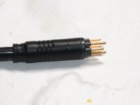
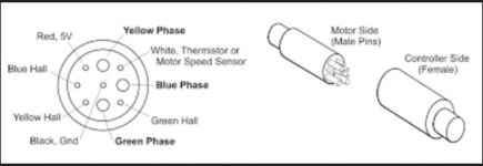
So, on to debugging - what's busted? Problem is, BikeBerry has no idea what's in the kit they sold me, so it's hard to test what might be wrong. When I look at the connector from the controller to the motor, one of the pins has carbon on it. I'm assuming that this pin shorted as the connector came loose. Looking online, there's a pinout for the Higo Z910 connector on this page: https://www.ebikes.ca/news/controller-motor-higo/ Assuming that this diagram is correct, and the top of the diagram corresponds to the arrow on the outside of the connector, the shorted pin is to the blue Hall sensor.

I'm not sure how to verify the hypothesis that the Hall sensor has blown and needs to be replaced. The connector doesn't make the hall sensor wires available for testing, and I have no information on what controller or motor I'm working with. Might anyone have suggestions on how I might proceed?

Thanks,

Katherine
 
One of those cases of getting what you pay for, hah.

Anyway if the higo connector just randomly fell out for no reason, i'd assume it's one of those clone of a clone of a clone type situations where it will be a perpetual problem. What's likely if it's *that* janky is that the wires leading to the little pins and slots are also soldered in a questionable fashion.

You can jiggle the motor cable while hitting the throttle to rule out something that is just barely loose..

You also can pull the controller and motor apart and check for continuity between each wire to the motor stator and hall sensors themselves & the higo connector to the controller board as well.

If i was in your shoes, i'd send the thing back since there is apparently no support, and the vendor should eat the cost of a broken kit for not knowing what they are selling and refusing to support it. Way too many companies hawking junk out there.
 
Higo plugs have to be pushed together pretty hard to engage fully. If the thing wasn't plugged all the way in, that would predispose it to have intermittent contact and/or arcing as well as accidental unplugging.
 
Try what Chalo suggested. Those two connectors do have to (a) be aligned correctly and (b) be firmly pushed together. The plug has to go all the way to the line under the arrow. That's about 14 inch.

P1120248.jpg

I have sometimes not fully seated them. Let's hope that you didn't plug it in hard enough.

It's pretty hard to plug together incorrectly. The three pins are longer and won't go into the smaller diameter holes, but it's possible if you plugged it in with the controller turned on, that you might have popped something if arrows were not matched. I believe some posters have managed that.

If the motor still doesn't work, perhaps you can convince the seller to send you another unit., maybe if you bear the shipping?

If someone in the family has some electrical skills, you can probe the motor end of the cable. Need some little clips, a 5-6 volt battery, and a 5V LED, or a voltmeter and some resistors.
 
The cable is well and truly seated. If you push it all the way in, it clicks. Shame on me for not checking it before I set out.

Bikeberry hasn't been a bit of help, and with the margin they're working on, no wonder. The only way they would send me another unit is to buy one from them. I might end up doing that anyway, if for no other reason than to swap out components to see if I can narrow things down.

I have a multimeter - I don't have resistors but they aren't hard to get. I haven't done electronics in a while, I'm a software engineer. But I have done, enough that I think I could replace a hall sensor without a problem. Except for the problem of figuring out what kind of hall sensors they are, but one problem at a time.

Thanks,

Katherine
 
If you take the motor apart, you should be able to measure the hall sensor voltages inside somewhere while the Higo is plugged in.
There are many sensors that will work. SS41A is one of the more common ones. But measure first.

It's possible the plug was not properly aligned one time and blew a sensor by miswiring.
 
personally i think it'd be easier to measure inside the controller, rather than teh motor. then you can still test the halls by spinning the motor, and don't have to deal with wires thru axles, potentail for damaging windings, etc.

most controllers just have the few screws on the fet bar, edge of controller, then the four to six screws on the endcap with the wires coming out. then slide out the board/etc.

as long as the board is not allowed to touch anything metal, and you don't put your fingers/etc on it, it's safe enought ot etest stuff on there with it on and running.

if a sensor is bad, they're pretty much all honeywell ss411a or some other variation of ss41x . the ss411a will work to replace any common ebike motor position hall sensor i've seen so far.


if there's actually burn on pins in the higo, that implies something shorted to a phase wire, as thats the only ghting that could have enoghv oltage and currnet to cause a burn. if a hall shorted to a phase wire, it probably did blow the hall.

conversely if the connector was turned and plugged in far enought o cnnect a phase from contrller to hall, if it also still had another phase connected to a motor phase and a nother motor phase connected to a contorler side hall signal, it coulc'fve fried something n the controller itself.
 
Agree somewhat with Amber.. If you have a helper read the meter and provide that third hand, you can probe it inside the controller.

Most manufacturers using the Higo connector follow the standard. Look for where the the thin yellow, blue, and green wires terminate on the circuit board. Measure between them and a ground reference. The thin black wire is ground. They will flip between 5V and 0V when the Hall's fire as the wheel is turned.

On the other hand if you have a helper, you can test on the motor plug ....We'll use Grin's pic.

pinout.jpg

5 volts (3 AA's in a holder) go to red/black. Put a LED and a resistor (I think 120 ohms will do) in series. Put the positive end of the LED on the 5 volts. Touch it to the negative end as a test. It should light. Then put the end of the LED/resistor to each of the hall pins in the above diagram. I believe the Hall's will fire the LED if they work. I could use a resistor and voltmeter, but that takes three hands again. If I get the LED working, it's easier.

I havem't done it myself, but I need to do this same test this week to check the the speed sensor (white wire) on my fatbike motor.
 
The cheap thing to try, is a new higo motor wire, if they can supply one.

If not, consider cutting off the burnt plug, and directly splicing the wires. That should get you going. Not too likely anything burnt, except the plug.

I agree, it might have been not fully plugged in originally, typically that is a real tight plug, and does not fall off. But so tight, it might seem fully plugged in when its not.


The sensor would be blown, if you ever put power on it, with the arrow aligned wrong. That would put 36v through a 5v hall sensor.
 
Don't even bother with buying from them.
Bikeberry is a gasoline bicycle kit Chinesium importer, who advertises in the gasoline bicycle forums.
If they have no idea what was in the kit that they sold you, then dont even bother with them anymore!

wolfalohalani said:
The only way they would send me another unit is to buy one from them. I might end up doing that anyway, if for no other reason than to swap out components to see if I can narrow things down.
 
Yes, get rid of that plug.

- Get a new razor blade, the thin ones and carefully slice 6" of insulation off, then carefully try to get each wire separated. Hopefully there isnt no foil, or metal sheething, I doubt it. Separate the thicker wires from the thinner wires. Hopefully they are different sizes. If not, then a new approach is necessary.


dogman dan said:
The cheap thing to try, is a new higo motor wire, if they can supply one.

If not, consider cutting off the burnt plug, and directly splicing the wires. That should get you going. Not too likely anything burnt, except the plug.

I agree, it might have been not fully plugged in originally, typically that is a real tight plug, and does not fall off. But so tight, it might seem fully plugged in when its not.


The sensor would be blown, if you ever put power on it, with the arrow aligned wrong. That would put 36v through a 5v hall sensor.
 
Wow, lots of great suggestions - thank you for giving me some avenues to explore. I hadn't considered just taking the connectors out of the equation by chopping them out and wiring the leads together, that's destructively brilliant, and I'd need to do something like that if the connectors are fried anyway. It's reassuring to know that if I end up replacing Hall sensors I have a replacement with a good chance of being the right one. And plenty of options for testing.

I don't think the cable got turned when I plugged it back in, and I don't think it was misaligned when I took the cycle out for a ride. So I'll hope that all that happened is that the hall got fried. Assuming testing bears that out, I'll try replacing one or more halls first, and then look more closely at the controller. It might be easier to just replace it rather than try to isolate problems on the board, but that might change if I manage to get any information on it.
 
There is a motor/ controller tester you can buy for 20 bucks, that will tell you if the halls work.

Fairly easy to test the halls in a motor too with just a voltmeter, especially after you take that plug off, and have bare wires to work with.

The halls wires are red and black power in, then blue, green and yellow power out. Put 4-5v into the red and black wires. red is +. Then with a voltmeter, put the leads on the black, and one of the b g y wires. A working hall sensor will turn the power on and off on the bgy wires, as you rotate the wheel. if its a geared motor, rotate the wheel in reverse.

You don't have to take the motor apart to test halls.
 
dogman dan said:
The halls wires are red and black power in, then blue, green and yellow power out. Put 4-5v into the red and black wires. red is +. Then with a voltmeter, put the leads on the black, and one of the b g y wires. A working hall sensor will turn the power on and off on the bgy wires, as you rotate the wheel.

With almost all motors, unless you have the controller hooked up, that won't work. Halls like those used in ebike motors, "bipolar latching" types, don't output any voltage, they only ground the voltage placed on their signal wires. The cotnroller has pullup resistors to the hall signals inside it, that provide the voltage for the halls to ground out when they activate.

So with the controller hooked up that would work, but because this controller / motor has a connector you can't probe without it being disconnected, it can't be tested that way without opening either the motor or the controller, or cutting open the insulation jacket on either the controller or motor cable, to give access to the conductors of the wires while still having hte controller's pullup resistors/voltages on the signal wires.


In the extremely rare case of having a board for the halls in the motor that also has pullup resistors on it, then the simple test using only the motor *will* work. Haven't seen one yet, though.
 
Yes you can take that connector out of the equation, but please cut each wire separately, and not all at once, and unplug the battery! Its a good technique to cut each wire individually, otherwise you may just cut all the wires off and the controller may have the capacitors charged up, or you cut the battery connector by mistake.


wolfalohalani said:
 
There is a chance the wire colors don't match on either side of the connector. If you decide to cut off the connectors, leave enough wire so you can strip back the jacket and still see the colors. Then you can trace the wire colors to the pins to make sure they match.
 
george1948 said:
Hello. i have installed a 36v battery 250w-350w to a 36v controller with 250w motor.When the battery isn't connected to the controller when i push the battery button the lights are opening but when i connect it to the controller it stop working. Please help me.

Check your polarity first. Positive on battery to positive on controller. Any ebike kit builder should own a volt-ohm-meter (and they measure current too). Take your meter and verify that you see +36V on the appropriate color leads.

Here I am, saying this. This afternoon I jumped the dead battery on my car off my daughter's car. "Red to red," I said as she watched, "Now black to black, Let's not crank my car. Let the battery charge". Within seconds, the cables started smoking. OMG I did it backwards, red to black.After some worrisome moments, it turned out I destroyed the jumper cables and blew a fuse in the radio, but I had a second set of cables. The car started and all seems well.
 
Back
Top