
You are using an out of date browser. It may not display this or other websites correctly.
You should upgrade or use an alternative browser.
You should upgrade or use an alternative browser.
Build No. 2 - Reduction Drive - now w/ NEW video
- Thread starter mauimart
- Start date
Warren said:Martin,
Your BB drive, MTB is spot on. Now tell us about the Manta!
http://www.youtube.com/watch?v=4H_6brrNGEM&list=UUP8AAVgO5574WFNGvfHVkzg&index=10&feature=plcp
Warren
More info here:
http://endless-sphere.com/forums/viewtopic.php?f=34&t=37911
https://sites.google.com/site/seaburyhallengineering/home/electric-car
Martin,
Thanks for the links. Probably need a wider front track for a three wheeler. I can't believe somebody hasn't yet successfully marketed an EV trike similar to this. Polaris now owns GEM. With 12 kWh pack, 30 hp, under 1000 pounds it would be a fun all weather commuter.
Warren
Thanks for the links. Probably need a wider front track for a three wheeler. I can't believe somebody hasn't yet successfully marketed an EV trike similar to this. Polaris now owns GEM. With 12 kWh pack, 30 hp, under 1000 pounds it would be a fun all weather commuter.
Warren
Just rigged-up a prototype rpm bar graph that may find its way on the bike. I will replace the Arduino with LM2907 (frequency to voltage converter) once it arrives. This will make those rapid gear changes more dramatic.
[youtube]B6vtIfTjB_s[/youtube]
[youtube]B6vtIfTjB_s[/youtube]
sn0wchyld
100 kW
mauimart said:Just rigged-up a prototype rpm bar graph that may find its way on the bike. I will replace the Arduino with LM2907 (frequency to voltage converter) once it arrives. This will make those rapid gear changes more dramatic.
[youtube]B6vtIfTjB_s[/youtube]
ha! awesome mate.
crossbreak
1 MW
Nice rev counter! Now try geting it on your bike  I have so much calbe on my bike, it makes most of the weight i guess lol. I hope the counter will work in your case, once used a similar one to count "sines" but it didn't I hope you have more luck. The speedict could do the job also, if it would measure phase currents, but it doesn't
I have so much calbe on my bike, it makes most of the weight i guess lol. I hope the counter will work in your case, once used a similar one to count "sines" but it didn't I hope you have more luck. The speedict could do the job also, if it would measure phase currents, but it doesn't Byte
1 kW
That RPM thingy is awesome! Where can I buy one? 
pff7
100 W
Can't find the 80-100 motor outrunner on HK, do they not have it anymore? and if not what would be equevalent?
Awesome video, being in fast motion was hard to tell how fast you were going though......and did you do the whole 2 hours without a recharge? I noticed some of those roads not having a shoulder really...but the scenery was very good.
Ive always thought using the existing drive train on the bike seems most efficient and smart.
pff7 said:Can't find the 80-100 motor outrunner on HK, do they not have it anymore? and if not what would be equevalent?
Awesome video, being in fast motion was hard to tell how fast you were going though......and did you do the whole 2 hours without a recharge? I noticed some of those roads not having a shoulder really...but the scenery was very good.
Ive always thought using the existing drive train on the bike seems most efficient and smart.
The 80100 motors seem to available at Leaders Hobby (http://www.leaderhobby.com/product.asp?ID=9394001224162).
With regards to the video, I did pedal a lot and my average speed was about 17mph. The only time I really 'opened it up' was after being passed by the car (8:21 in video) where I did 40-45mph for a brief stint.
pff7
100 W
Cool.....I bet at 17mph you got way more distance with your batteries.And the pedaling helped too....I also like pedaling my power-assisted bikes , wouldn't have it any other way.(I have gas also)
Thankyou for the link...not a bad price comparing to the greyborg.The specs I believe say power=6500 Watts. But you mentioned the bearings not being to good though.....very good thead.
Thankyou for the link...not a bad price comparing to the greyborg.The specs I believe say power=6500 Watts. But you mentioned the bearings not being to good though.....very good thead.
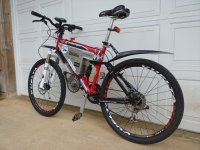
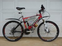
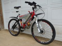
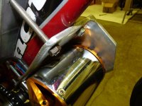
Here's the bike with the latest additions. The front fork is a Fox F-Series RL which is orders of magnitude better than the stock POS. A set of fenders should help make my commute a bit more bearable as the rainy season approaches. The fenders are Topeak DeFender and I shortened the front fender so as not to interfere with the motor.
I'm calling the bike pretty much complete. If I get my hands on a controller that is smaller than the Kelly yet with the same power output, I could fit another 3 bricks of 6S, 5Ah Lipo inside of the battery box for a total of 1kWh (18S, 15Ah). The only limiting factor on the bike is motor temperature. That being said it is a competent hill climber and does fine on the road at 45mph. I plan to do some testing while monitoring motor temp to see what kind of continuous power it can take without overheating. I have already installed an internal temp sensor which I will feed into an Arduino based data logger. The logger will also read the CA data and that way I will be able to see which operating conditions produce the greatest increases in heat. If there was an easy way to effectively get the heat out of this motor (who hasn't heard that before), it would be the perfect e-bike...
I'm calling the bike pretty much complete. If I get my hands on a controller that is smaller than the Kelly yet with the same power output, I could fit another 3 bricks of 6S, 5Ah Lipo inside of the battery box for a total of 1kWh (18S, 15Ah). The only limiting factor on the bike is motor temperature. That being said it is a competent hill climber and does fine on the road at 45mph. I plan to do some testing while monitoring motor temp to see what kind of continuous power it can take without overheating. I have already installed an internal temp sensor which I will feed into an Arduino based data logger. The logger will also read the CA data and that way I will be able to see which operating conditions produce the greatest increases in heat. If there was an easy way to effectively get the heat out of this motor (who hasn't heard that before), it would be the perfect e-bike...
Attachments
h0tr0d
1 kW
- Joined
- Apr 28, 2012
- Messages
- 460
mauimart said:.....If there was an easy way to effectively get the heat out of this motor (who hasn't heard that before), it would be the perfect e-bike...
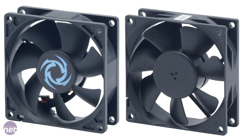
My 2 cents, 80mm pc fan glued to the rotor, forcing air in....?
What do you think about eliminating the rear cassette freewheel so that the motor is always getting air even with no load (with the above fan)? Regen braking and shifting without accelerating or pedalling as bonuses...
Perhaps even an air scoop!!

Can you share some about that Arduino "CA" and rpm meter? wiring diagrams, code, parts... Saw a lot of interest around here!
Awesome build again!!
thanks,
h0rt0d
crossbreak
1 MW
Can you share some about that Arduino "CA" and rpm meter? wiring diagrams, code, parts... Saw a lot of interest around here!
also highly appreciated!!
h0tr0d said:My 2 cents, 80mm pc fan glued to the rotor, forcing air in....?
I've thought of something like this but decided to try one of Thud's centrifugal fans that will draw the air from one end of the motor out through to the other. I will post updates once I get some results.
h0tr0d said:Can you share some about that Arduino "CA" and rpm meter? wiring diagrams, code, parts... Saw a lot of interest around here!
h0rt0d
I have a number of arduino based e-bike projects going all of which are in an incomplete or buggy state. Once I feel the designs are mature enough, I can post some more details.
crossbreak
1 MW
I have a number of arduino based e-bike projects going all of which are in an incomplete or buggy state. Once I feel the designs are mature enough, I can post some more details.
Thanks for that! I'll try to get into this also. Recently bought an android phone, hope I can reactivate my programming skills.
h0tr0d
1 kW
- Joined
- Apr 28, 2012
- Messages
- 460
My idea: Remove the rotating part of the 92mm fan (my bad ) and glue it to the 80100 rotor with a plastic sleeve around to force the air into the motor.

Didn't explained explain my idea well enough, sorry...
Thud's fan shows awesome craftsmanship but bad design in two ways: straight blades and sucking hot air instead of pushing cold air. Curved fan blades are more effective and pushing in is a lot better because it's denser, therefore, great cooling effect.
Of course, you could test both options (real conditions temp monitoring and no load current) to compare.
Regarding your Arduino stuff, I wonder if could start a topic with what you have so far, me and crossbreak could "copy" and help improve. I've got a few friends with great prog skills that could help us.
) and glue it to the 80100 rotor with a plastic sleeve around to force the air into the motor.
Didn't explained explain my idea well enough, sorry...
Thud's fan shows awesome craftsmanship but bad design in two ways: straight blades and sucking hot air instead of pushing cold air. Curved fan blades are more effective and pushing in is a lot better because it's denser, therefore, great cooling effect.
Of course, you could test both options (real conditions temp monitoring and no load current) to compare.
Regarding your Arduino stuff, I wonder if could start a topic with what you have so far, me and crossbreak could "copy" and help improve. I've got a few friends with great prog skills that could help us.
pff7
100 W
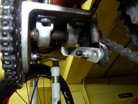
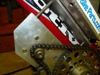
On top of page 2, regarding jack shaft gears, is that a piece of L shape aluminum or metal? Looks nice and shiny , was wondering what and how much machining/welding you had to do? Sick bike parts free wheel assembly am assuming. You mentioned rpm's in the order of 6000 max?
pff7 said:On top of page 2, regarding jack shaft gears, is that a piece of L shape aluminum or metal? Looks nice and shiny , was wondering what and how much machining/welding you had to do? Sick bike parts free wheel assembly am assuming. You mentioned rpm's in the order of 6000 max?
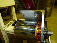
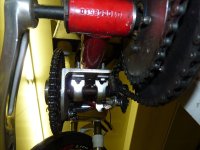
Yes, the motor mount is stock L-shape aluminum (3-1/2 x 3-1/2 x 1/4 inch). It's clamped onto the downtube with a flat plate of 1/4 inch aluminum on the top of the tube. All of the "machining" was done using a cutting blade on a right angle grinder. The drilling was done using a drill press and hand drill. The only welding I did was in the construction of the battery/controller box. The box is simply bolted onto the aluminum plate that sits above the down tube. If I wanted to I could dismantle the whole drive train and restore the bike to its original donor condition, which by the way will never happen.
The freewheel crank is from Sick Bike Parts. The jackshaft also has a freewheel but I can't remember where I got it. It should be in the thread somewhere. Max rpm unloaded is about 4750 rpm @75V off the charger.
Here are some close-up photos.
Attachments
pff7
100 W
Beautifull maumart, that L-stock aluminum looks a handy-dandy. Half of this game seems to know where to source these materials for these builds and I'm not going to ask you to spoon feed me, I need also to build a jack shaft capable of not getting in the way of pedal crankshaft. Thanks for the close-ups, looking at them makes me notice that motor looks not so small after all.
Byte
1 kW
mauimart said:Just rigged-up a prototype rpm bar graph that may find its way on the bike. I will replace the Arduino with LM2907 (frequency to voltage converter) once it arrives. This will make those rapid gear changes more dramatic.
[youtube]B6vtIfTjB_s[/youtube]
Have you done this completely by yourself? Or was there a tutorial or something on the internet? Could you please share it?
Byte,Byte said:Have you done this completely by yourself? Or was there a tutorial or something on the internet? Could you please share it?
No tutorial unless you consider the internet the mother of all tutorials.
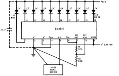
The circuit is comprised of two cascaded LM3914N bar graph drivers connected to two 10-segment LEDTECH LL10000 bar arrays. The general schematic for the drivers and LED's is taken directly from the data sheet (see below). The arduino, using an interrupt routine, calculates rpm and then converts to an analog output via PWM and outputs through an R-C low pass filter which provides the signal source for the LM3914. My sample code is attached. It's very crude and not very well commented but may be enough to give you an idea of what is going on. The next step, when I get more time, would be to add some code that would allow the user to easily change some parameters in order to configure for varying motors and rpm ranges. Hope this helps.
Martin
Code:
// E-bike RPM bar graph display using 2 cascaded LM3914N display drivers

volatile byte rpmcount;
 unsigned int rpm;
 unsigned long timeold;


int pwmPin = 9; // output pin supporting PWM
//  int inPin = 3; // voltage connected to analog pin 3, e.g. a potentiometer for testing
int val = 0; // variable to store the read value
float volt = 0; // variable to hold the voltage read
void setup()
{
pinMode(pwmPin, OUTPUT); // sets the pin as output
analogWrite(pwmPin, val);
attachInterrupt(0, rpm_inter, RISING);  //interrupt 0 is digital pin 2
   rpmcount = 0;
   rpm = 0;
   timeold = 0;
}
void loop()
{
if (rpmcount >= 21) {
     //Update RPM every 21 counts (3 revolutions), increase this for better RPM resolution,
     //decrease for faster update
 //    rpmcount = rpmcount/7;  //7 pole pairs on C80100
     rpm = (8571/(millis() - timeold))*rpmcount;  // 7 pole pairs 60/7=8.571 -> 8.571*1000 = 8571
     timeold = millis();
     rpmcount = 0;
 //    Serial.println(rpm,DEC);
     val = rpm/30;   //4000 rpm = 50% duty cycle = 128
     analogWrite(pwmPin, val);
   }
if ((millis() - timeold) >= 500)  {
analogWrite(pwmPin, 0);
}

}
void rpm_inter()
 {
   rpmcount++;
 }
Attachments
Similar threads
- Replies
- 1
- Views
- 272
- Replies
- 12
- Views
- 581
- Replies
- 2
- Views
- 266
- Replies
- 4
- Views
- 188