
That's a nifty idea; it could be used on regular ebike/etc controllers as well, using a transistor to invert the signal and operate the keyswitch/ignition/enable line to shutdown the MCU/gatedrive on those.
You are using an out of date browser. It may not display this or other websites correctly.
You should upgrade or use an alternative browser.
You should upgrade or use an alternative browser.
Building a 100% DIY ESC for motors
- Thread starter thorlancaster328
- Start date
parabellum
1 MW
thorlancaster328
I would go trough Arlo's treads, all of them, time you have waiting for parts, there are a lot of underwater rocks you could eliminate, without burning thousands of USD on components to get there. If you get Highhopes to look at your project, he can provide you a huge short-cut to success. I think Fets current rating is not the main problem in your "topology".
I would go trough Arlo's treads, all of them, time you have waiting for parts, there are a lot of underwater rocks you could eliminate, without burning thousands of USD on components to get there. If you get Highhopes to look at your project, he can provide you a huge short-cut to success. I think Fets current rating is not the main problem in your "topology".
thorlancaster328
100 W
- Joined
- May 25, 2018
- Messages
- 197
So what do you think the main problem is with my design? When It burned the first time, I was using 60mΩ P-channel FETs. WAY too high.
For the powerstage of my new controller, I have pretty much copied Lebowski's power stage. I have looked at several commercial ESC schematics and they all are nearly identical aside from part numbers AFAIK.
With the bootstrap capacitor circuit, I will have to maintain a minimum drive frequency, above 10hz to be safe. This should never be an issue, as the software will not allow full throttle at lower RPMs. Good for the FETs and the torque arms/dropouts too!
parabellum
1 MW
Topology.
thorlancaster328
100 W
- Joined
- May 25, 2018
- Messages
- 197
What do you mean by topology?
In my old ESC, the Vcc and ground traces snaked around quite a bit. In this version, the Vcc and ground traces are straight and reinforced by heavy gauge wire.
In my old ESC, the Vcc and ground traces snaked around quite a bit. In this version, the Vcc and ground traces are straight and reinforced by heavy gauge wire.
zombiess
10 MW
fechter said:The conduction losses are the primary source of heat and only depend on current. Switching losses will go up with voltage. Overall, you won't see much change with higher voltage unless your switching times are too slow.
I^2*R loses are dominant at high duty cycle, but at low DC Vds (diode) loses dominate (can be countered with synchronized switching). You will always have some diode losses due to reverse and forward diode recovery, even with sync switching. Switching loses remain pretty much constant, but DC bus and higher inductance in the power pass layout seems to have some effect due to the amount of over and under shoot that occurs during turn off and on. How fast you switch a given device mainly determines how lossy it will be because it's about how fast you can get through the mosfets transconductance region (Miller plateau). Switching frequency also determines losses. High switch freq like 80khz will have much more loses than 16khz.
parabellum
1 MW
Board design is one of most critical steps at those and any power levels.thorlancaster328 said:What do you mean by topology?
Known to work BOM will eventually fail at some level on a perfboard or bad board design.
thorlancaster328
100 W
- Joined
- May 25, 2018
- Messages
- 197
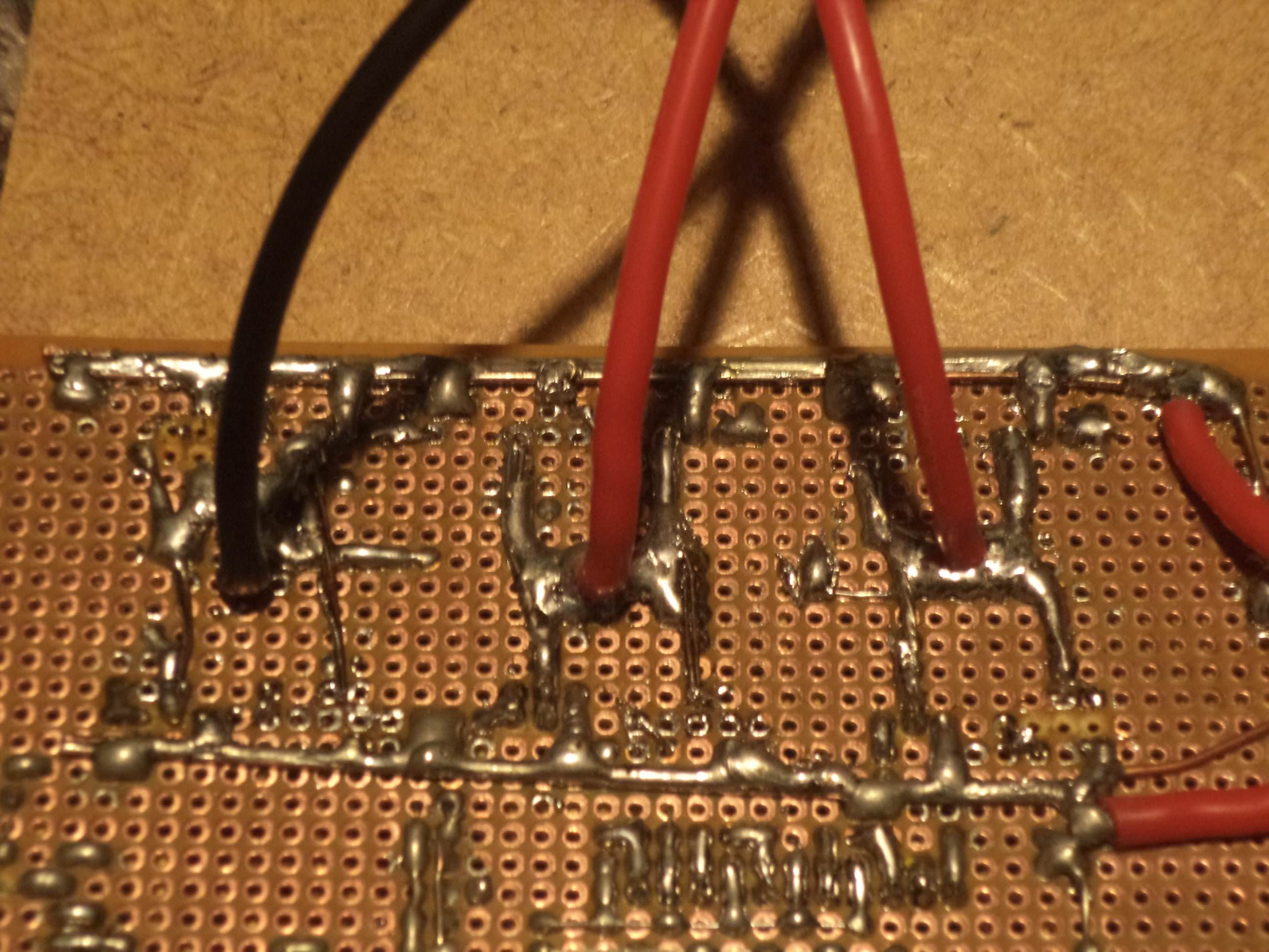
I've completed the back side of board attempt #2 and here is the layout of the power section. The power wires are on the right, and the three phase wires are sticking straight up. The FETs will be on the other side, with the leads and all associated wiring as short as possible.
Based on an online resistance table, the resistance of the each power trace should be around 1 milliohm. There will be 1000uf and 0.47uf bypass caps on the other side and the legs of the big cap will be beefed up with 14awg copper until they hit the main power buses. The small capacitor's legs will be on the left and they will be only a couple of mm long.
Previously, I bought some IRF3205 FETs off of eBay and they were obvious fakes. The internal resistance was about 5x to 10x what it should have been. Those FETs are now in the garbage where they belong
The genuine Infineon FETs should arrive next Wednesday, from Arrow Electronics. Quite a bit more expensive but they're a certified distributor and their shipping is free (for now).
If I added a straight heavy gauge wire in parallel with the skinnier power trace on the other side of the board, would that help current capacity? Or would it just create a ground loop?
thorlancaster328
100 W
- Joined
- May 25, 2018
- Messages
- 197
About a week ago, the FETs arrived. I soldered them in, and... It didn't work! I did a little probing and one of the 3 NCP5181 gate driver chips was blown. I ordered some more, and they arrived a few days ago.
I installed them and tested the board against a RC brushless motor hooked up to a propeller. It easily handled 15 amps with only a 10 degrees Celsius temperature rise in two minutes, no fan. At the end of the test, I felt the motor and it was extremely hot. Like 3rd degree burn hot. Pretty weird for a motor that I have ran at twice the current, huh?
Today, I put it on my bike wheel and gave it a spin. A terrible grating "WRRRWRRRWRRRRWRRR" sound came from the motor and the amp readings went through the roof. 20 amps just to turn a wheel is absurd, and something was horribly wrong.
It wasn't topology. The power traces are extra beefy and straight as an arrow.
It wasn't bypass capacitors. I have them literally everywhere.
It wasn't blown FETs. The wheel runs happily at very low speeds with no missing whatsoever.
I dialed the power down to zero and realized what the problem must be. THE BRAKE!!!
When powered up, the wheel has lots or turning resistance. When powered down, there is no rolling resistance. Due to some odd bug in my code, the e-brake functionality is stuck at ON. I guess that explains the crazy amp draws, the burning propeller motor, and the unexplanable amp spikes. I'll be gone for a vacation for about a week. When I come back, I'll fix the code, polish it up, add a fancy OLED display, and if all goes well, write a tutorial on how to make one within 2 weeks from now. (Warning: It'll be a hard project).
After the bike-motor-brake escapade, the MOSFETs weren't even perceptibly warm. I'm glad I have genuine IR FETs in this circuit.
thorlancaster328
100 W
- Joined
- May 25, 2018
- Messages
- 197
Its been a while.
I arrived home from my camping trip and got to work on the ESC the next day. It wasn't running right
I found a loose connection and "fixed" the problem. I twisted a potentiometer hooked up to the throttle pins, and the motor started with a loud gzgzsgzgzgz-wrrrrrRRR-wrrRRR-wRRrrrrrrrrrrrr. Normally, the motor starts up with next to no noise at all on the factory controller.
Given that I had a 10 amp fuse in line with the battery, I decided to give it full throttle.
The motor accelerated and spun at a nice high speed. Unfortunately, it was extremely loud and vibrated the entire bike. It was also drawing several hundred watts and the controller was getting quite warm.
For the next FIVE HOURS I fiddled around with the direction, speed, motor choice, phase hookup, sensor hookup, control loop factors... but to no avail. I gave it a test ride and it struggled to get me up to 5 mph without triggering the overheating protection (conservatively set at 60°C).
The solution to the problem:
After fixing the problem, the motor ran silently and efficiently, drawing only 5 watts at full speed and running just as silently as the factory controller. There was a thunderstorm about an hour ago and there are puddles everywhere, so I'll probably test ride it tomorrow.
**EDIT to not bump this thread again**
The controller drives the motor smoothly, but the FETs get pretty hot. 10 amps continuous is about as high as I'd want to go. The FETs are really good, 8mOhm IR parts that should be able to do 50 battery amps without even getting warm. I don't have a scope so I can't debug it any more.
Next time I have the time/money, I'll build one of the Lebowski designs and modify it after I get it working.
I arrived home from my camping trip and got to work on the ESC the next day. It wasn't running right
I found a loose connection and "fixed" the problem. I twisted a potentiometer hooked up to the throttle pins, and the motor started with a loud gzgzsgzgzgz-wrrrrrRRR-wrrRRR-wRRrrrrrrrrrrrr. Normally, the motor starts up with next to no noise at all on the factory controller.
Given that I had a 10 amp fuse in line with the battery, I decided to give it full throttle.
The motor accelerated and spun at a nice high speed. Unfortunately, it was extremely loud and vibrated the entire bike. It was also drawing several hundred watts and the controller was getting quite warm.
For the next FIVE HOURS I fiddled around with the direction, speed, motor choice, phase hookup, sensor hookup, control loop factors... but to no avail. I gave it a test ride and it struggled to get me up to 5 mph without triggering the overheating protection (conservatively set at 60°C).
The solution to the problem:
Two weeks ago, when fiddling with phase advance, I had set it all the way to 60°. I thought I had changed it back, but I had forgotton to. The small red motor that I had posted earlier in this thread worked just fine with the crazy phase advance (It's a RC motor designed for it). On the other hand, the high Q-factor, low Kv Ebike motor just had asthma attack after asthma attack on the phase advance.
After farting around with all of the regular settings, I hooked up a small OLED to the controller's i2c line and had it print out several things, including the commutation phase it was currently in. When I set the throttle to a low value and manually turned the wheel slowly, there was a "sticky spot" each time the motor changed what phase it was driving. That also explained the instability and hihh current consumption my bike was suffering, due to reverse-powering each phase for a short time, with the current only limited by the motor resistance. I bet I was getting upwards of 30 or 40 amp, microseconds-long current peaks through the phases due to commutating 60° too EARLY
After farting around with all of the regular settings, I hooked up a small OLED to the controller's i2c line and had it print out several things, including the commutation phase it was currently in. When I set the throttle to a low value and manually turned the wheel slowly, there was a "sticky spot" each time the motor changed what phase it was driving. That also explained the instability and hihh current consumption my bike was suffering, due to reverse-powering each phase for a short time, with the current only limited by the motor resistance. I bet I was getting upwards of 30 or 40 amp, microseconds-long current peaks through the phases due to commutating 60° too EARLY
After fixing the problem, the motor ran silently and efficiently, drawing only 5 watts at full speed and running just as silently as the factory controller. There was a thunderstorm about an hour ago and there are puddles everywhere, so I'll probably test ride it tomorrow.
**EDIT to not bump this thread again**
The controller drives the motor smoothly, but the FETs get pretty hot. 10 amps continuous is about as high as I'd want to go. The FETs are really good, 8mOhm IR parts that should be able to do 50 battery amps without even getting warm. I don't have a scope so I can't debug it any more.
Next time I have the time/money, I'll build one of the Lebowski designs and modify it after I get it working.
Similar threads

- Replies
- 6
- Views
- 814
- Replies
- 26
- Views
- 1,933
- Replies
- 14
- Views
- 271