Hummina Shadeeba said:
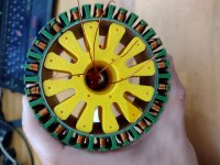
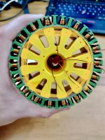
I think in the center would get better heat transfer with more contact between the stator and aluminum. (Assuming the 3d print ends up aluminum)
This is a toss up. For 3D print, the air flow will be much better and the air contact with the stator better. With CNC aluminium, I am not sure which way the tradeoff would go. Probably a bit of aluminium would help. The optimium would be to extrude a heatsink with fins profile as the hub, but I am not likely to invest in that any time soon. Maybe if this works out so well I start selling motors :lol:
Got a chance to spinny spinny tonight. I love SimonK escs. Sometimes I wonder why I don;t just stick one of those chips to a mega power stage and call it job done.
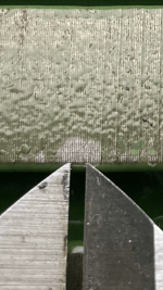
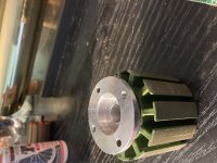
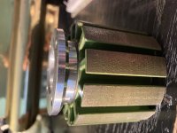
Unfortunately, it rubs horribly seemingly because the 3D print material creeps over a few days. It did not rub when I built it up and last posted

Need to invest in metal. This seems good enough, promising enough, that a few machined parts might be worth their cost for actual use
[youtube]TKR6NggJY0k[/youtube]
https://youtu.be/TKR6NggJY0k in case it doesn;t render for anyone
The harmonic content in star is good.
.jpg")
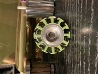
The kV with just 6 turns works out as 38!!! Iron stator FTW

It was very very clear that Delta is not as good as star. Just by connecting the wires in Delta, I could feel the extra resistance when not connected to the ESC. In star, it (obviously) spun very freely.
Running it in Delta was awful, the ESC got really hot and it drew 60W while only going fairly slowly. In star, the speed and losses were fairly low, there are clearly recirculations going on in Delta.
I had always read that Star needed care to get the winding correct (which ones you fix together) and indeed my first try was wrong, but it was easy to figure out with the scope - the wrong winding drew a triangle wave on the scope, and flipping it over made 3 nice smooth sinusoids.
Delta I had read could be connected in any way, reversing a phase would merely reverse the direction of the motor. Can someone confirm this is true? It is not obvious to me that it is. The Delta connection was SO bad compared to star that I feel like it must be an error. I'll have a go at a few combinations (all of them) tomorrow and see if I can get a better result.
EDIT: 5 minutes after posting this, it is clear that my assumption on delta is bollox, just thinking about 3 arrows 120 degrees apart for the vectors, it cannot be the case that swapping any one around is OK.


 , and hopefully it won't take me that much time to get the ESC back working.