Burned the fuse in battery

Cyclomania

10 kW
Joined
May 22, 2022
Messages
514
Location
Northern Europe
Hi

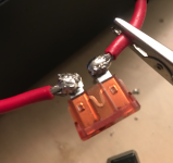
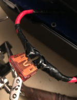
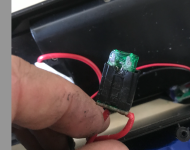
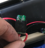
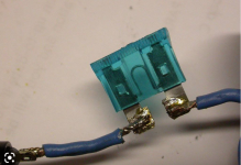
I think I blew the fuse (?) in my ebike battery riding quite hard uphill with a slightly too strong controller perhaps.

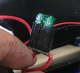
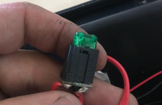
Looks like in the picture. Any idea on what and how to change this? It is kind of melted into the black and green there. Can I just cut it off with a knife and solder on something different? And if so, what should I use?

Thanks
 

Attachments

  • Skärmavbild 2022-08-05 kl. 11.58.08.png
    Skärmavbild 2022-08-05 kl. 11.58.08.png
    623.5 KB · Views: 858
  • Skärmavbild 2022-08-05 kl. 11.58.04.png
    Skärmavbild 2022-08-05 kl. 11.58.04.png
    651.2 KB · Views: 858
  • Skärmavbild 2022-08-05 kl. 11.58.00.png
    Skärmavbild 2022-08-05 kl. 11.58.00.png
    1.1 MB · Views: 858
  • Skärmavbild 2022-08-05 kl. 11.57.55.png
    Skärmavbild 2022-08-05 kl. 11.57.55.png
    1,021.8 KB · Views: 858
E-driver_ said:
It seems like most fuse holders are only 30amps and that the volts are mostly up to 32volts.

What do you guys use for 36-52volt batteries? Fuse holders I mean. I only find those glass fuses above 30 amps.
a few threads, if theyre useful
https://endless-sphere.com/forums/search.php?keywords=fuse*&terms=all&author=&sc=1&sf=titleonly&sr=topics&sk=t&sd=d&st=0&ch=300&t=0&submit=Search
 
Voltron said:
Maybe check out a boating supply place, they usually have options on high amp fuses.
51N6JVqRGXL._AC_SY1000_.jpg202354FUS-80.jpg

Or you might have to go with a resettable circuit breaker.

Yeah good idea.

This is the best I have found so far on Aliekspress.

https://www.aliexpress.com/item/4001054699610.html?gatewayAdapt=4itemAdapt

But still a bit large to fit inside an ebike battery this one.
 
Voltron said:
Looks good, as long as the quality control is ok.

I have now received the fuse and am thinking about soldering it onto the cable inside my battery.

Now, I was a bit surprised that this fuse which is stated as 40a is looking smaller and less robust than the one I bought from a store in Scandinavia.

Look at this picture below. The old fuse(to the left) with less A is bigger and the cables are more robust. But that perhaps does not matter for making the right one stronger? So I could just go on and solder it on witout any second thoughts? Or should I worry about the thinness?
 

Attachments

  • Skärmavbild 2022-12-23 kl. 10.54.19.png
    Skärmavbild 2022-12-23 kl. 10.54.19.png
    1.7 MB · Views: 260
The fuse on the left does indeed have thicker wires, but that could be because of wire material, stranded vs solid wire, wire thickness, and surrounding insulation. The only factor that really matters for current capacity is cross sectional area of conductor.
Also, since it's a fuse, the fuse will pop before the wire fails. Is the conductor of the new fuse same or similar to your battery wire?
 
It should pop first, but the whole point of this post though is how his original one melted down before it popped. And maybe his second one too?

The big issue is the contacts inside the body. If they're cheap metal, they lose springiness after heating cycles, then get such bad connection resistance they melt down, esp with a higher amp fuses. It hardly ever happens on a 10 or 15 amp... They pop first before the heat gets bad.

I hate to say it but I think that new one will be a risk too... It's a different one than you had in the last link?
Screenshot_20221223-085856.png
 
E-driver_ said:
Voltron said:
Looks good, as long as the quality control is ok.

I have now received the fuse and am thinking about soldering it onto the cable inside my battery.

Now, I was a bit surprised that this fuse which is stated as 40a is looking smaller and less robust than the one I bought from a store in Scandinavia.

Look at this picture below. The old fuse(to the left) with less A is bigger and the cables are more robust. But that perhaps does not matter for making the right one stronger? So I could just go on and solder it on witout any second thoughts? Or should I worry about the thinness?

The one on the left looks underrated and the one on the right looks overrated and a knock off of the 40A versions with 10 AWG wire (looks like they used 12AWG, maybe 14AWG). If you go up a size to the maxi fuse style, there would be more surface area between the fuse legs and sockets, so maybe less of an issue with poor connections that generate the heat:
https://www.amazon.com/2PCS-Holder-Waterproof-line-Gauge/dp/B09ZX5VYRP/ref=sr_1_16?crid=74YFFPJE4ITB&keywords=automotive+fuse+holder&qid=1671818176&sprefix=automotive+fuse+holder%2Caps%2C188&sr=8-16
 
Voltron said:
It should pop first, but the whole point of this post though is how his original one melted down before it popped. And maybe his second one too?

The big issue is the contacts inside the body. If they're cheap metal, they lose springiness after heating cycles, then get such bad connection resistance they melt down, esp with a higher amp fuses. It hardly ever happens on a 10 or 15 amp... They pop first before the heat gets bad.

I hate to say it but I think that new one will be a risk too... It's a different one than you had in the last link?
Screenshot_20221223-085856.png

That one has not arrived yet unfortunately. But I have another one too. The to the right below.

I think that one might be better?
 

Attachments

  • fuse.png
    fuse.png
    1.2 MB · Views: 216
Just by looks, I'd go with your Scandinavian one, assuming the actual wires under the insulation are about the same.
It has the beefier look, like at least they weren't skimping on every extra bit of material.
 
Voltron said:
Just by looks, I'd go with your Scandinavian one, assuming the actual wires under the insulation are about the same.
It has the beefier look, like at least they weren't skimping on every extra bit of material.

Hmm I will have to wait for the other fuse to arrive.

The scandinavian one melted the last time. So I think I will try this one below(the one at the top with completely red is the same as the second picture that has black and red color).

I think I will use this one(picture). It says it can tolerate 48-60volts.

Only trouble is it is 14AWG. But maybe it will work. What do you think?

At the bottom is the most powerful one that has not yet arrived. Perhaps I should wait for this one to arrive? Or do you think the one above might do?
 

Attachments

  • Skärmavbild 2022-12-31 kl. 12.30.07.png
    Skärmavbild 2022-12-31 kl. 12.30.07.png
    858.2 KB · Views: 158
  • Skärmavbild 2022-12-31 kl. 12.33.23.png
    Skärmavbild 2022-12-31 kl. 12.33.23.png
    1.8 MB · Views: 157
  • Skärmavbild 2022-12-31 kl. 12.33.30.png
    Skärmavbild 2022-12-31 kl. 12.33.30.png
    834.5 KB · Views: 157
E-driver_ said:
The scandinavian one melted the last time. So I think I will try this one below(the one at the top with completely red is the same as the second picture that has black and red color).

I think I will use this one(picture). It says it can tolerate 48-60volts.

Only trouble is it is 14AWG. But maybe it will work. What do you think?

At the bottom is the most powerful one that has not yet arrived. Perhaps I should wait for this one to arrive? Or do you think the one above might do?

Just solder the conductors directly to the fuse blades ang cover them with heat shrink. No holder needed.
 
E-HP said:
E-driver_ said:
The scandinavian one melted the last time. So I think I will try this one below(the one at the top with completely red is the same as the second picture that has black and red color).

I think I will use this one(picture). It says it can tolerate 48-60volts.

Only trouble is it is 14AWG. But maybe it will work. What do you think?

At the bottom is the most powerful one that has not yet arrived. Perhaps I should wait for this one to arrive? Or do you think the one above might do?

Just solder the conductors directly to the fuse blades ang cover them with heat shrink. No holder needed.

Hmm. You mean like this picture below? And then cover them up with electric tape kind of?

But if the fuse cannot pop up from something, will it even activate? Or is that something that happens inside of the fuse?
 

Attachments

  • Skärmavbild 2022-12-31 kl. 15.22.57.png
    Skärmavbild 2022-12-31 kl. 15.22.57.png
    731.5 KB · Views: 146
Yes, it's all in the fuse. Nothing actually moves, like with a circuit breaker.
The skinny wire inside just vaporizes when it blows.
The problem with direct soldering is that is you can't just pop a fuse in to get running again.

I have no idea of this would work, but maybe make your own holder with wires soldered to spade terminals that are good quality, then insulated, so that you could still pull the fuse out if needed?
(Like the picture, but for bigger wire)
Screenshot_20221231-080924.png
 
Re waiting for the better one, a big difference in those is that the plastic they're made of is much stiffer and less heat sensitive than the rubbery looking ones. They encapsulate the contacts much better from what I've seen in use.

Cutting the skinny attachment wires closer to the fuse helps reduce heating too. The shorter an undersized length of wire is, the less it will contribute to the fuse holder trying to heat up.

Re. the red one, it says in the data sheet it's for charging. That would make me automatically worry about using in a power wire.
 
Voltron said:
Re. the red one, it says in the data sheet it's for charging. That would make me automatically worry about using in a power wire.

Yeah perhaps because they make a bit of a strange translation form chinese to english? I think it is a regular fuse.

Voltron said:
Re waiting for the better one, a big difference in those is that the plastic they're made of is much stiffer and less heat sensitive than the rubbery looking ones. They encapsulate the contacts much better from what I've seen in use.

Aha ok. Perhaps I will do the red one first and try it out. I need to practice soldering anyway :)


Voltron said:
Cutting the skinny attachment wires closer to the fuse helps reduce heating too. The shorter an undersized length of wire is, the less it will contribute to the fuse holder trying to heat up.

You mean to cut off the wires on the sides of the fuse, correct? So it is more only the fuse and fuse holder. With shorter wires on the sides, right?
 
E-HP said:
E-driver_ said:
Hmm. You mean like this picture below?

Yes, that's the idea.

Hmm I am going to try the fuse with holder first to see if it works well. Since I am curious to see if it works. But this idea is very good. When I am building my 52volt-battery, later this winter, I could try this one right? Because in that battery I am thinking of having a fuse of like, perhaps 60amps. I am going to use hg2-cells in that one.
 
Yes... Shortening the stock wires coming out of the fuse holder.

And usually when it's a charger accessory, it's usually not as high a power rating as something meant for going from a battery to a controller. You hardly ever see charging amps over 10 or 15, but 2 or 3 times that draw on the power wires is pretty common.
 
Voltron said:
Yes... Shortening the stock wires coming out of the fuse holder.

And usually when it's a charger accessory, it's usually not as high a power rating as something meant for going from a battery to a controller. You hardly ever see charging amps over 10 or 15, but 2 or 3 times that draw on the power wires is pretty common.

I am going to try that on this one. Shortening the wires coming from the fuse holder as much as possible. Then I am going to see if this works well for a while.

Then I am going to use the E-HP-solution on another battery, because I think that was an interesting solution as well. Did not even know it was possible to just solder the fuse straight to the wires like that.
 
What a day. First tried to solder on the fuse and holder. That was too big too be able to close the battery after. So I went with the soldering onto wires-method instead.

Made a couple of mistakes but finally it looked like this. Probably looks like shit right? But seems to be working so I am quite content.
 

Attachments

  • Skärmavbild 2023-01-01 kl. 17.36.16.png
    Skärmavbild 2023-01-01 kl. 17.36.16.png
    1 MB · Views: 68
  • Skärmavbild 2023-01-01 kl. 17.36.06.png
    Skärmavbild 2023-01-01 kl. 17.36.06.png
    1.5 MB · Views: 67
amberwolf said:
How do you plan to change the fuse when it blows on a ride?

Just cut it off. Solder on a new one.

But hopefully this is the sweetspot. Hope it does not go over 40a. Last one was 30a. But I am not sure if the actual fuse was activated there, or if the holder just melted, as Voltron talked about. Something had definately melted in there. But I am not sure if that is what activated it. It activated during a very steep slope I was riding up.
 
E-driver_ said:
amberwolf said:
How do you plan to change the fuse when it blows on a ride?

Just cut it off. Solder on a new one.
That's only possible on a ride if you either carry a portable soldering iron capable of enough heat to do the work, or you happen to be close enough to an outlet to use your wall-powered iron (and carry that with you on every ride).

A fuseholder would make repair much easier. ;)

The disadvantage of the fuseholder is that it can cause the problem you started with in this thread....
 
Worst case scenario if it blows on the road, you could strip the wires with a knife, then twist the whole thing around until the wires touch and it would bypass the fuse temporarily to limp home.
And you're probably right in that sweet spot... Just enough amps to melt a holder, but not quite enough to blow the fuse 🤣

It's not anything you're doing wrong btw. It just shows their amps ratings on the holders is a lie.
 
Back
Top