ThatCanabianGuy420
1 µW
- Joined
- Jun 3, 2017
- Messages
- 4
Hello from Hamilton Ontario!
Long time "lurker", FIRST time poster hoping to get some help. I have an Emmo S6 E-Bike (details to follow). It is powered by a 72v (32 +-1A)(2300W?) controller (again details to follow). I have searched everywhere, including these forums, for as much info as I can get about this controller. Before you ask, yes, I DID try to contact the manufacturer with no success.
What I am specifically looking for is the ability to activate regen braking, and reverse. I have found (by process of elimination and trial and error...and luck) which wire pair activates the "cruise control" feature (listed below) and what seems to be a "low speed limiter" of some sort (walk assist?). There are three wires on the board which go to PB1, MH, and PB2. I assume these are the low-med-hi "speed" ranges (which I could care less about as it seems the MH is semi-permanently connected to ground, which I believe (and hope), is just keeping it in "HI" all the time).
I would like as much help and information as you kind and knowledgeable people have to give.
E-Bike Information:
2016 Emmo S6
Factory 60v Upgraded to 72v batteries and controller
Motor is their so called "500 Watt Super Torque Motor" - Handles much more. Actual wattage unknown. (Shall try contacting Emmo Toronto for more info)
Brakes - Hydraulic disk front, drum rear.
Wheels/Tires - 10" x 3.50 by Kenda
Controller Information:
72v 32 +-1A (Small 1/4 shunt mod added...current current unknown.)
Model: DDL15R
Manufacturer: http://www.wxri-seu.com (Wuxi?, Xufeng?)
Caps: 100v
FETS: 15 x MagnaChip MDP1991 100v (120A supposedly)
CPU: CY8C24533-24PVXI Cypress Semiconductor Corp - M8C PSOC 8-Bit 24MHz 8KB ( 8K x 8 ) FLASH 28-SSOP


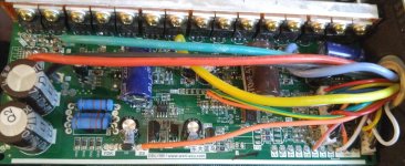
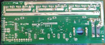
Looking at the board there are several things that are clear, and others that are...well...not at all. Some of the items such as the phase and power connections, hall sensors, and throttle are all quite easy to find even without labels. Some of the items are a little less obvious... There are connections for an alarm, and also (hidden under the cap above the main IC) what I believe is the programming port (Can be seen from the back side just above TP-MT, between the hall inputs and what I believe is the lo-med-high switch).
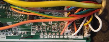
The thick pink wire from DS is for cruise control. The thin pink wire from BK is EABS. There is also a white wire pair (that I ASS-umed might be the self learn feature...) that actually enables a very LOW speed limit on S or E (or both) (walk assist?) There is a yellow wire with a bullet connector that has no (or very very low) voltage coming off of MT(ground, blown, or NC? )
)
From what I understand about the processor almost every pin on it can be configured to be an input or output in programming. This makes defining what pin is responsible for what...almost impossible for someone that knows so much less about these things than some of you fine folks on here.
Is there any way to find out what pin is responsible for what without having the ability to read/write to the processor or view the corresponding code? I understand that there are tools for reading/writing to PSoC devices, of which I have none of them, and even if I did...I would not know if this chip can be reprogrammed or if it is locked and I would have absolutely no idea where to start as I have ZERO experience in programming.
Anyone have experience with this controller or the processor it contains? Would love absorb your knowledge...
Now for PART TWO!!! LOL (And you thought it was already long....)
IMO at first glance, judging by the components and spec sheets, it seems that the FETs likely could not handle the claimed 120 Amps (especially without additional cooling - even if they COULD) but they SHOULD be okay to run 60 - 80 amps? I have drilled holes in the controller casing as it was not allowing enough cooling under high amp/load, low speed conditions (which obviously I try to avoid). I have plans to add an additional small 12v pc cooling fan to the casing and run it off the 72-12v 10A converter.
The bike has decent enough speed. If I want a little more speed I know I can SAFELY over-volt this controller to 84 volts without issue. What I want is more TORQUE. I have two IDENTICAL Emmo S6's. The other bike has 72 volts worth of batteries at the moment on a 60 volt controller. Even if I drop that bikes controller to it's intended 60 volts, the off-the-line torque and acceleration is MUCH better than this bikes, even though the bike in question runs at LEAST 5kmph (almost 10kmph) faster... What I found odd was that both controllers (very different makes) could have the same "amp limit" yet one CLEARLY puts out more than the other. I assume this is some sort of "ramping" effect controlled by programming more than by hardware setup?
So...I have added some thin copper wire ( wound through all three shunts sort of like a figure 8 ) to one quarter of the shunt, on the controller currently in question, in an attempt to get slightly more current out of it without over-doing it right off the start. I would like to be somewhere around 60 - 70 amps for this bike...I think. I still have not tested this mod to see if it has made a difference.
Here's the question(s): Am I on the right path with attempting to mod the shunt on this controller? From what I understand...If I "mod" half of the shunt it should put out DOUBLE the current current, correct? Are there any alternatives for getting the controller to put out more amps?
Sorry for the SUPER long post. Looking forward to the opinions and comments from all of you!
Regards,
ThatCanabianGuy
Long time "lurker", FIRST time poster hoping to get some help. I have an Emmo S6 E-Bike (details to follow). It is powered by a 72v (32 +-1A)(2300W?) controller (again details to follow). I have searched everywhere, including these forums, for as much info as I can get about this controller. Before you ask, yes, I DID try to contact the manufacturer with no success.
What I am specifically looking for is the ability to activate regen braking, and reverse. I have found (by process of elimination and trial and error...and luck) which wire pair activates the "cruise control" feature (listed below) and what seems to be a "low speed limiter" of some sort (walk assist?). There are three wires on the board which go to PB1, MH, and PB2. I assume these are the low-med-hi "speed" ranges (which I could care less about as it seems the MH is semi-permanently connected to ground, which I believe (and hope), is just keeping it in "HI" all the time).
I would like as much help and information as you kind and knowledgeable people have to give.
E-Bike Information:
2016 Emmo S6
Factory 60v Upgraded to 72v batteries and controller
Motor is their so called "500 Watt Super Torque Motor" - Handles much more. Actual wattage unknown. (Shall try contacting Emmo Toronto for more info)
Brakes - Hydraulic disk front, drum rear.
Wheels/Tires - 10" x 3.50 by Kenda
Controller Information:
72v 32 +-1A (Small 1/4 shunt mod added...current current unknown.)
Model: DDL15R
Manufacturer: http://www.wxri-seu.com (Wuxi?, Xufeng?)
Caps: 100v
FETS: 15 x MagnaChip MDP1991 100v (120A supposedly)
CPU: CY8C24533-24PVXI Cypress Semiconductor Corp - M8C PSOC 8-Bit 24MHz 8KB ( 8K x 8 ) FLASH 28-SSOP


Looking at the board there are several things that are clear, and others that are...well...not at all. Some of the items such as the phase and power connections, hall sensors, and throttle are all quite easy to find even without labels. Some of the items are a little less obvious... There are connections for an alarm, and also (hidden under the cap above the main IC) what I believe is the programming port (Can be seen from the back side just above TP-MT, between the hall inputs and what I believe is the lo-med-high switch).
The thick pink wire from DS is for cruise control. The thin pink wire from BK is EABS. There is also a white wire pair (that I ASS-umed might be the self learn feature...) that actually enables a very LOW speed limit on S or E (or both) (walk assist?) There is a yellow wire with a bullet connector that has no (or very very low) voltage coming off of MT(ground, blown, or NC?
From what I understand about the processor almost every pin on it can be configured to be an input or output in programming. This makes defining what pin is responsible for what...almost impossible for someone that knows so much less about these things than some of you fine folks on here.
Is there any way to find out what pin is responsible for what without having the ability to read/write to the processor or view the corresponding code? I understand that there are tools for reading/writing to PSoC devices, of which I have none of them, and even if I did...I would not know if this chip can be reprogrammed or if it is locked and I would have absolutely no idea where to start as I have ZERO experience in programming.
Anyone have experience with this controller or the processor it contains? Would love absorb your knowledge...
Now for PART TWO!!! LOL (And you thought it was already long....)
IMO at first glance, judging by the components and spec sheets, it seems that the FETs likely could not handle the claimed 120 Amps (especially without additional cooling - even if they COULD) but they SHOULD be okay to run 60 - 80 amps? I have drilled holes in the controller casing as it was not allowing enough cooling under high amp/load, low speed conditions (which obviously I try to avoid). I have plans to add an additional small 12v pc cooling fan to the casing and run it off the 72-12v 10A converter.
The bike has decent enough speed. If I want a little more speed I know I can SAFELY over-volt this controller to 84 volts without issue. What I want is more TORQUE. I have two IDENTICAL Emmo S6's. The other bike has 72 volts worth of batteries at the moment on a 60 volt controller. Even if I drop that bikes controller to it's intended 60 volts, the off-the-line torque and acceleration is MUCH better than this bikes, even though the bike in question runs at LEAST 5kmph (almost 10kmph) faster... What I found odd was that both controllers (very different makes) could have the same "amp limit" yet one CLEARLY puts out more than the other. I assume this is some sort of "ramping" effect controlled by programming more than by hardware setup?
So...I have added some thin copper wire ( wound through all three shunts sort of like a figure 8 ) to one quarter of the shunt, on the controller currently in question, in an attempt to get slightly more current out of it without over-doing it right off the start. I would like to be somewhere around 60 - 70 amps for this bike...I think. I still have not tested this mod to see if it has made a difference.
Here's the question(s): Am I on the right path with attempting to mod the shunt on this controller? From what I understand...If I "mod" half of the shunt it should put out DOUBLE the current current, correct? Are there any alternatives for getting the controller to put out more amps?
Sorry for the SUPER long post. Looking forward to the opinions and comments from all of you!
Regards,
ThatCanabianGuy

