E-bike build Overvolting dd hub motor

aj353519

10 µW
Joined
Mar 30, 2024
Messages
6
Location
Maryland
Greetings,
I'm new here and I wanted to discuss my exact setup. Also my potential setup with the new motor and controller I ordered. This is my second build.
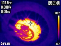
I started with 14s lipo on a 1000w 48 volt 26in direct drive hub motor setup. The controller that came with the kit I'm assuming was a 1000 watt controller. I did a shunt mod. I had to remove some of the solder because the controller kept cutting out. But I found a happy medium. I have an amp meter in line between the battery and controller. I upgraded the controller to a 2000 Watt and did a shunt mod on that. I went from 14s to 20s lipo. Now running 84 volts. With the current controller, motor and battery setup the system regularly draws a maximum of 42 amps. I did some math on that...3,528w.... Maximum speed 43 miles per hour. So this motor is taking an additional 2,500 Watts without failing. That's a neat trick. It gets warm but never hot to the touch. I just ordered a 2,500 watt controller and a 1500 watt 48 volt motor. The torque specs on the original motor was 27NM. Maximum rotating speed 460 RPM. The new motor is 55 NM and 500 RPM. I'm looking to hit 50 mph with the new motor and controller. From my understanding the motor decides the amount of current it pulls from the battery and controller. As long as the controller can handle the volts and the amps the motor will draw whatever it wants. I am very pleased with my current setup but I need to achieve 40 mph as a cruising speed due to the roads in my area. My current cruising speed is around 30 mph. I can climb steep grades at 16 to 17 miles an hour. While my current setup was good it's not enough for me. I guess my only question is am I crazy for trying to run something like this? Allowing the motor to take triple The watts and almost twice the voltage? I do not feel like my current motor is at risk for burning up. I just disassembled it yesterday and it shows no signs of damage. Is this common practice in the e-bike community? As far as over-volting and overcurrent is concerned? I would like to upgrade to a 3000 w fat tire setup, but my financial limitations only allowed me to take this middle step with the 1500 watt 48 volt motor. I have purchased a motor from this company on my first build and did the same thing with overvolting and upgrading the controller and had no issues. The reason I'm upgrading my current setup is mainly the lack of torque. Wind drag and hills prevent me from reaching my desired necessary cruising speed. My one way distance commute is 1.7 MI. So I'm not really looking to run long and hard on the motor, just quick and fast to get me there in traffic without having to ride on the side of the road or on the sidewalk. Although the speed of it is 40 mph people regularly speed. I just need to be able to keep up with traffic. This stretch of road though is only a third of my total commute. And is at the beginning so I'm always freshly fully charged. I'm curious to see how many amps this 1500 watt motor will draw with the 2500 watt controller. I'm actually surprised that the 2000 watt controller that I have now has not fried considering it's pushing almost 4,000 watts out regularly. Side note. When I opened up my new 2000 watt controller for the first time to do a shunt mod there was already solder applied to the shunts. Not really sure what that's about. But I added more anyways and was happy with the results. So yeah I just wanted to talk about my build and ask a couple questions because none of my family or my job or my girlfriend understands anything about this type of stuff and I've got no one to talk to about it LOL.
 
What are you using for cooling? With Statorade I ran my cheap old eBay 1000w MXUS up to 6kW peaks. 7kW+ peak on my 1500w, I limit it to 6 kW. If you have a temp sensor installed, you can put a lot of watts through a DD motor.
 
Okay. Statorade looks good. I will be making that purchase. As far as the temperature sensor goes I can pick one of those up. (See below)Should I be mounting the sensor inside the motor or just externally? It kind of seems like a daunting task to be able to get the wire through the axle with the other wires in place. I couldn't find a video on somebody doing it.1000000349.jpg
 
And if I'm going to be pulling the wires out of the axle I'll be upgrading them in the process. Only seems like the right thing to do. I didn't mention it earlier but my whole system is ran in 10 gauge silicone wire. Even the phase wires are 10 gauge up until about 2 in outside of the axle.
 
Okay. Statorade looks good. I will be making that purchase. As far as the temperature sensor goes I can pick one of those up. (See below)Should I be mounting the sensor inside the motor or just externally? It kind of seems like a daunting task to be able to get the wire through the axle with the other wires in place. I couldn't find a video on somebody doing it.
There are several posts on the forum, so you may be able to find a good tutorial using the search tool.
I got these because they are really small, like a large grain of rice:
I pushed it in between some space between the windings and glued it with JB Weld. I was lucky that my motor had a sensor, just not one used commonly, and not embedded in the windings, so I just used that conductor (you only need one wire, since the ground it already present because of the halls).

EDIT: I saw this on YT. Not very detailed, but covers the basic steps in fast motion. He drills the axle hole opening, but not sure if you want or need to do that.
 
I am very pleased with my current setup but I need to achieve 40 mph as a cruising speed due to the roads in my area.

No you don't. That's not what bicycles, pedal or electric, are for.

Best option is to develop a decent pair and ride accordingly. Fallback is to switch to a motorcycle.
 
So this next question is relation to my build. I run a 100 w LED white chip with a 60° lens as a headlamp for my e-bike. My current setup is 4S 12 volt SLA with a buck converter set to 34 volts. Issue number one is slas are heavy and the ones that I acquired were used and do not hold a good charge. I'm getting ready to replace my main battery, which is a 16 amp hour 20s lipo Bank. My plan is to use some of the old cells as power for my headlamp and other accessories (brake light, turn signals, phone charger, fan for cooling the LED). I'm looking to buy a boost converter rated 40 amps with the input output voltages within my plan range. Now my dilemma is I know that the bigger the voltage difference the lower the output current. But I have no way of knowing the actual difference without setting it up and testing it. My question is can I run 4S lipo, boosted the 34 volts, and still be able to create the three amps necessary to run the LED light. Or will there not be enough current because the voltage Gap is too big. How many cells do I need to be able to supply the adequate current on the output side of the boost converter.? I'm only throwing this out here because somebody might know about this I'm not sure where else online I can ask about it. Thanks in advance!
 
It seems like a 100W LED white chip with a 60° lens that you need a fan to keep cool would blind oncoming drivers. Also, do you really need to charge your phone on your 1.7 mile commute at 40 mph? I probably sound like a grumpy old man, and I am one, but it is a little frustrating to read this stuff because it is what gives e-bikes a bad reputation and causes local authorities to crackdown on all e-bike riders. You could easily buy or build an e-motorcycle that safely meets your requirements.

I would recommend getting an e-bike or motorcycle specific headlamp with a shaped beam to avoid blinding oncoming traffic. Motorcycle headlamps and taillights are designed to run on 12V and shouldn't need a voltage converter with the batteries you want to use.
 
This page may be useful to prevent loss of your investment (or worse):
 
From my understanding the motor decides the amount of current it pulls from the battery and controller. As long as the controller can handle the volts and the amps the motor will draw whatever it wants.

Not exactly, the motor is limited by the controller. The controller acts like a tap, it limits the maximum power that the motor is asking for.
What you describe is the case where the controller is way more powerful than the motor, in which case the motor draws whatever it can, indeed.

I am very pleased with my current setup but I need to achieve 40 mph as a cruising speed due to the roads in my area. My current cruising speed is around 30 mph. I can climb steep grades at 16 to 17 miles an hour.

The easiest way to achieve this is to go for a higher voltage, like you did. But now I think you're limited by the controller. If you need more speed I suggest you buy a controller that can do flux weakening. Flux weakening allows you to go for a higher speed than whatever your motor is rated for, at the expense of an increase in power consumption.

I guess my only question is am I crazy for trying to run something like this?

Hard to say, you didn't provide any picture of your ride. Some bikes are suitable for high speeds, some aren't. At this point we can't really guess.

Allowing the motor to take triple The watts and almost twice the voltage?

Here again, it's hard to say, we don't know what motor you have.
Some motors can tolerate more than ten times their rating. For example I'm running my 2000W QS205 motor at 22000W right now.
But some motors just can't take more power, for example I started with a 1000W no name motor and it burned out with a 3000W controller.
Different brands, different stator versions...

I do not feel like my current motor is at risk for burning up. I just disassembled it yesterday and it shows no signs of damage. Is this common practice in the e-bike community?

Yeah, I guess.

As far as over-volting and overcurrent is concerned? I would like to upgrade to a 3000 w fat tire setup, but my financial limitations only allowed me to take this middle step with the 1500 watt 48 volt motor. I have purchased a motor from this company on my first build and did the same thing with overvolting and upgrading the controller and had no issues. The reason I'm upgrading my current setup is mainly the lack of torque.
Getting a higher power motor helps a lot with torque. 1500W isn't really a significant upgrade from a 1000W motor, it would have probably been wiser to wait a bit more to get a 3000W.
Also, the brand and motor version matter, not all motors are created equal.

Wind drag and hills prevent me from reaching my desired necessary cruising speed.
I can't say for the hills, but I don't think wind drag limits you all that much at such low speed. I think what's limiting you is either your controller or the motor back EMF.
But again, without knowing much about your actual bike it's just a wild guess.

my whole system is ran in 10 gauge silicone wire
I did the same mistake, thought that it was a good idea to use silicone insulated wire... Problem is, silicone is extremely weak, you can probably cut it with a banana.
PVC is less fancy but a lot tougher. In my opinion the best is teflon, but it's a bit expensive. PVC is the best compromize cost/durability.

I know you probably don't want to hear this, but you might want to consider changing back to PVC if you can, that might avoid you some trouble somewhere in the future.
My question is can I run 4S lipo, boosted the 34 volts, and still be able to create the three amps necessary to run the LED light.
I suppose you can, if you can find an appropriate boost converter. But I wouldn't recommend to do that. Just take the power from your main battery and avoid all the unnecessary complexity, the added weight, the failure points. There's really zero benefit in adding another separate battery system for this.

I just did something similar on my motorcycle using two 100W LED chips, drawing current from the main battery through a buck converter with constant current/constant voltage set at around 34V just like you. Works great.

So yeah I just wanted to talk about my build and ask a couple questions because none of my family or my job or my girlfriend understands anything about this type of stuff and I've got no one to talk to about it LOL.
Welcome to the forum then!
 
20s lipo is 84 volts. I've looked but I can't seem to find a buck converter for that rating. Otherwise I would definitely just run the auxiliary system off of the main battery. Save me hassle and weight.
 
20s lipo is 84 volts. I've looked but I can't seem to find a buck converter for that rating. Otherwise I would definitely just run the auxiliary system off of the main battery. Save me hassle and weight.
The one I used it supposedly good for 95V, hopefully you can find something similar wherever you live:1711950674301.png
 
a controller that can do flux weakening
is this what others call 'field weakening'?

If so, people will know they are the same subject when searching. I hadn't myself heard the term 'flux weakening' before (so I might learn something too).
 
Statorade is a must, no question. Temp sensor will allow backing down or automatic rollback when the temp spikes.
I disagree. Hub sinks. Hub sinks can do more if you are just buying one or the other. Hubsinks > Statoraid.

I logged my 1000w motor to determine this... over its lifespan of 20k miles+ .... at 8kW peaks. The Statoraid did next to nothing to dissipate heat: Where the hub sinks did.
 
Greetings,

I guess my only question is am I crazy for trying to run something like this? Allowing the motor to take triple The watts and almost twice the voltage? I do not feel like my current motor is at risk for burning up. I just disassembled it yesterday and it shows no signs of damage. Is this common practice in the e-bike community?


No , not crazy. I ran 8x the rated power in a hub motor for years. At twice its rated voltage, 2x the continuous current, and 5x the peak current recommended by the manufacturer.

My current hub motor, a 3kW rated hub, takes 4x this number in peaks.

Join us on facebook in the group " Strictly Hub Motors "..: You will see thousands of people doing just that.

A good battery that doesnt sag much under load should get you closer to 50mph. Calculate kV, dia, and RPM, unloaded RPM is directly proportional to voltage, loaded RPM is a proportional product of power and load.
 
is this what others call 'field weakening'?

If so, people will know they are the same subject when searching. I hadn't myself heard the term 'flux weakening' before (so I might learn something too).
Ah Yeah, sorry I make this mistake because the Sabvoton controller interface called it flux weakening and that was my first controller so I often mix up the two terms. I'm not sure which one is the correct term to use as English isn't my first language.
I logged my 1000w motor to determine this... over its lifespan of 20k miles+ .... at 8kW peaks. The Statoraid did next to nothing to dissipate heat: Where the hub sinks did.
This contradicts a bit my own experience, In my tests the statorade didn't prevent temperature to rise, but it dit help to cool it down a whole lot faster. It rises at about the same rate but then it drops very quick. The motor covers get noticeably hotter. Maybe you didn't put enough of it for the statorade to correctly bridge the gap?

But I've always been concerned about the effects it can have on the magnets, since they become the main path for heat to travel.
I should have recorded the no load speed before and after using it, in order to see if the magnet strenght dropped or not. Maybe I'll try to do that on my next motor experiments.
 
Last edited:
I disagree. Hub sinks. Hub sinks can do more if you are just buying one or the other. Hubsinks > Statoraid.

I logged my 1000w motor to determine this... over its lifespan of 20k miles+ .... at 8kW peaks. The Statoraid did next to nothing to dissipate heat: Where the hub sinks did.
Interesting, I have totally oppisite results. Statoraid made a lot of difference, hubsinks almost nothing.
That is with a qs 205 50h 4t, 500pA and 3-400bA I think it was. Peaks about 24kw if I remember correctly.
 
Interesting, I have totally oppisite results. Statoraid made a lot of difference, hubsinks almost nothing.
That is with a qs 205 50h 4t, 500pA and 3-400bA I think it was. Peaks about 24kw if I remember correctly.
When it comes to motor heating, the neodymium magnet is more critical to heat, where temperatures above 80 degrees Celsius can cause its demagnetization, while the winding temperature on the stator can reach 150 degrees or more.
In this case it is important where these magnets stand inside or outside the motor, in the case of a wheel motor the magnets stand outside and are well cooled, their temperature rarely exceeds 60 degrees Celsius in hot seasons and long (several hours) loads.
 
I am talking about outrunners here, dd hubs. That is what I expect this question is about, on other motors it will be different. I dont think I ever saw over 60 degrees on the outside, even when the windings were about 140degrees. It got a few degrees warmer on the outside with statoraid. I think it was like it got to maybe 50 degrees before, then with statoraid it got to about 55 degrees before the windings got 140 degrees.
 
Here is some reading on the subject:
 
I am talking about outrunners here, dd hubs. ...

I dont think I ever saw over 60 degrees on the outside, even when the windings were about 140degrees. I
Yes yes my friend. Yes i speak of large DD hubs too. QS 205, I have studied 3x extensively, the 35H and the 50H. V1 and V3. I have also studied a 25H 1000w motor. Hey maybe different methods yield different results. I datalog internal temp, and have temps sensors on the inside and outside. 10x a sec. So. Three sensors and thermal cameras. Datalogged to .XLS. I have seen internal readings hitting the 200*C certainly. 140* (internal) would be insignificant for me.


I have read Justins thread on the cooling of hub motors. certainly. Thankyou for the link.

Plus an engineer to do the fin calculations. registered, insured, practicing, ASME certified.

I have seen the outside of the hub MUCH higher than 60*C.

I also do not sell statoraid, either.

Professionally so I will consider Justins results biased. I do not think you can consider a study " definitive " based upon the seller's claims. Biased, telling you the metrics, in hope for increased sales. There are certainly reports of statoraid gumming up the inside of the hub once it dries out: heat sinks do not " dry out" so to speak. No mention of this in the study : Alone this discredits the study. Another consideration,: is water in the hub. water can get into hubs ( as many of us know) and the mix of water and statoraid does nothing for longevity: Hubsinks also work when the internals of the hub are wet. Water does not dissipate the effectiveness of a heat sink.

Most certainly the entire reason for the study, to sell more statoraid, not to make an accurate representation. You see this in the consumer world often. I have yet to see a definitive assessment: unbiased: the definition of an " independent report" as to the efficacy.


So. In my personal and professional opinion. Sketch's Hubsinks > Justin's Statoraid.

Just an opinion based on my experiences, friend.


Here is a thermal picture of ( one of ) my hub(s) under testing. 50*C on the external. I will upload more when I get them off of this disk. ... and onto my SSD. I know I have significantly higher readings than this on the exterior. I must find the pictures.

Current consumption on my V3 50H hub is in the range of 80-120wH/mile. Provides excellent speed and very little residual heating at this level of consumption. About 6 sec to 60mph. Could be more, could be less,. I do not lug, bog, or lope the motor. I (personally) think this is a more important metric to watch out for in ANY installation. A loping motor: is a hot, unhappy, motor.
 

Attachments

  • Img_09_03_2022_11-56-07.jpg
    Img_09_03_2022_11-56-07.jpg
    53.9 KB · Views: 1
And if ... I'll be .... Only seems like .... I didn't ....in 10 gauge silicone wire. .... are 10 gauge up until about 2 in outside of the axle.


The increase of the diameter of the phase conductors...... is negligible in my opinion. very little losses in the phase wire. NBPower sells a hub motor rated at 5000w with smaller wires than the QS 3000w motor. Literally like... 3mm ea... dia... ....yet still does 5000w easily. The QS motors use larger ( about 7mm in dia) ......the QS are typically considered under rated.

I once upgraded the 2.5mm^2 phase leads on a generic 1000w motor to try to make more power... it was not easy, drilling out the axle on the lathe, and stuffing 3x ( 10awg) in the place..... very hard to do this. Axle is simply not large enough for me. i used THHN wire. Much less diameter insulation than a silicone insulation. ... A 10AWG THHN takes more current than a 12AWG silicone.... and the 12AWG silicone is much larger diameter than the THHN, in 10AWG.

3Delta 3wire.... , Phase to GND, kW(1), Phase to GND, kW(2),
kw1+kW2 = kW Total.
 
When it comes to motor heating, the neodymium magnet is more critical to heat, where temperatures above 80 degrees Celsius can cause its demagnetization, while the winding temperature on the stator can reach 150 degrees or more.
In this case it is important where these magnets stand inside or outside the motor, in the case of a wheel motor the magnets stand outside and are well cooled, their temperature rarely exceeds 60 degrees Celsius in hot seasons and long (several hours) loads.


Certainly not. 80*C is not demagnetizing the hub.

I run well over 200* C peaks, and I certainly reach a stabilized temperature of 150*C +... on the winding sensor. No detriment to the magnetic flux from the motor.

In fact, here is the QS published magnet grade chart.. and they DO NOT lose magnetisim at 80*C as you quote...... they withsand double that, ( 160*C!) even at a 100% or greater duty cycle.

QS magnets are listed as SH35. I do not think I have seen anything near this high on the hubs I have tested.. on the magnet ring... yes I agree here. ....the magnet ring is very well cooled... but there is measurable heat transfer.

The higher the heat of a thermal transfer, the greater the efficincy. Wellknown factor of heat engine design. Also applies to elecrical motors.
 

Attachments

  • 93245932_3263215963708710_8655883295139037184_n.jpg
    93245932_3263215963708710_8655883295139037184_n.jpg
    109.7 KB · Views: 2
Back
Top