Custom BLDC Controller Closed Loop

Hey Again Guys!

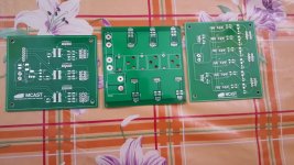
So work has been ongoing and each time I think my PCB design is done, I change something. Having said that my gate driver board and supply board are done. The only thing that's left to be finalized for now is the Inverted board. This will allow me to test the motor in open loop. The sensing board will come later.

Having said that, if anyone technical is reading this, I need your help!

I am trying to work out what size heat sinks I need for my transistors. Attached you can find the MOSFET's datasheet that I am using, an application note which outlines how to calculate the mosfet's power losses and the calculations I made using the Excel Sheet. (Note: the supply voltage is 48V and the motor current shall be 20A)

In the excel sheet the cells in bright pink I am not 100% sure if I took the correct reading on them so this is why I need your help. Also provided that my calculations are correct, what is my next step in choosing a heatsink? I was thinking to bend the transistors so the case(back) would be facing upward, and I would bolt a 10cm by 10cm by 0.5cm aluminium plate as a heatsink to all the transistors similar to a cpu cooler if this would be able to dissipate the heat made. Else I was think that on top of the plate I would also connect an old GPU cool I have lying around if the plate alone is not enough.

What are your thoughts?

Thanks in Advance
 

Attachments

  • Heat Sink Calculations.xlsx
    11.5 KB · Views: 35
  • IRLI3705N N-Channel Mosfet.pdf
    112.7 KB · Views: 32
  • 70-41484.pdf
    799.6 KB · Views: 42
Hey everyone!

I am making my own controller for a 1kW motor and I have almost done the PCB design for my inverted board but I need to see what size heat sinks I need to finalize the size.

I am trying to work out what size heat sinks I need for my transistors. Attached you can find the MOSFET's datasheet that I am using, an application note which outlines how to calculate the mosfet's power losses and the calculations I made using the Excel Sheet. (Note: the supply voltage is 48V and the motor current shall be 20A)

In the excel sheet the cells in bright pink I am not 100% sure if I took the correct reading on them so this is why I need your help. Also provided that my calculations are correct, what is my next step in choosing a heatsink? I was thinking to bend the transistors so the case(back) would be facing upward, and I would bolt a 10cm by 10cm by 0.5cm aluminium plate as a heatsink to all the transistors similar to a cpu cooler if this would be able to dissipate the heat made. Else I was think that on top of the plate I would also connect an old GPU cool I have lying around if the plate alone is not enough.

What are your thoughts?

Thanks in Advance
 

Attachments

  • 70-41484.pdf
    799.6 KB · Views: 41
  • Heat Sink Calculations.xlsx
    11.5 KB · Views: 47
I see your mosfet choice handles up to 55V. It seems a bit too low, since a fully charged LiFePO4 (48V - 16S) pack will output 59,2 V hot off the charger and drop to 57,6 later. Which exceeds your fet maximum Vds rating.
 
mateusleo said:
I see your mosfet choice handles up to 55V. It seems a bit too low, since a fully charged LiFePO4 (48V - 16S) pack will output 59,2 V hot off the charger and drop to 57,6 later. Which exceeds your fet maximum Vds rating.

Now that you say that I will charge my battery to see what voltage it goes up to but when it arrived it was at 50V and I assumed it was fully charged. I will do the test and check.

Thanks a lot for the info!!

But what I am looking for right now is just a way to sort out the heat sink issue!
 
glenn0010 said:
mateusleo said:
I see your mosfet choice handles up to 55V. It seems a bit too low, since a fully charged LiFePO4 (48V - 16S) pack will output 59,2 V hot off the charger and drop to 57,6 later. Which exceeds your fet maximum Vds rating.

Now that you say that I will charge my battery to see what voltage it goes up to but when it arrived it was at 50V and I assumed it was fully charged. I will do the test and check.

Thanks a lot for the info!!

But what I am looking for right now is just a way to sort out the heat sink issue!
Heatsink is pretty easy, not that i have any experience, but as big as you can fit seems fine haha.
 
mateusleo said:
Heatsink is pretty easy, not that i have any experience, but as big as you can fit seems fine haha.

Haha that's what I would like to do but it's not an option, It wouldn't look too good in my thesis without any calculations, + my lecturer has already told me this haha.

So I have to know the size via calculation + its a good learning experience.
 
Drunkskunk said:
You might consider the IRFB3077 instead of the 3705. The 3077 can handle up to 75 volts, and has an Rds of 0.0028 instead of 0.0120, it's also rated for up to 120 amps, instead of just 52.

That means it will handle your voltage better and run cooler.

Ohhhh damn I like this transistor! I think I just might change to this one. Even tough I bought the other ones and this one is more than 4 times the price per transistor I think I'll go for it!

Good find !

You don't know anything about the heat sink calculations do you?

Thanks a lot
 
glenn0010 said:
mateusleo said:
Heatsink is pretty easy, not that i have any experience, but as big as you can fit seems fine haha.

Haha that's what I would like to do but it's not an option, It wouldn't look too good in my thesis without any calculations, + my lecturer has already told me this haha.

So I have to know the size via calculation + its a good learning experience.
As you insist in calculating, read Fundamentals of Heat and Mass Transfer by Frank P. Incropera, chapter one is enough for you application, its pdf is easily found to download. Once you estimate the size, use atleast the double, those books don't take many relevant aspects in into account.Maybe you'll have to look for aluminium or whatever alloy you are using heat related constants on google. How many amps are you going to need ? IRFI4410 (http://www.irf.com/product-info/datasheets/data/irfi4410zpbf.pdf) seems interesting for this, handles higher voltage than previous, has a bit lower DS resistante and also has isolated package, so you don't have to worry about short-circuiting the fets though the heatsink, they'r a bit pricey ($4 each for small amounts) but good stuff.
 
Hey thanks for the transistor suggestions. I think I will go with the IRFB3077. It has very low Rdson very high current and voltage handling capabilities. Also very good thermal resistance compare to the others. Just to confirm it is an N-channel mosfet correct?
 
glenn0010 said:
Hey thanks for the transistor suggestions. I think I will go with the IRFB3077. It has very low Rdson very high current and voltage handling capabilities. Also very good thermal resistance compare to the others. Just to confirm it is an N-channel mosfet correct?
Yeah, it seems like N-channel. Just be careful because it has no isolated package, so you can't simply mount all the fets on the same chunk of metal heatsink unless you use some kind of isolant between the body and the heatsink and use plastic screws to screw it on because the package is directly connected to the drain (or source, can't remember now which one), so if you don't isolate them when screwing into the heatsink, u'll probably short them out. Very low DS resistance, nice choice =D

Would you mind to e-mail me your thesis when you're done? I'd appreciate. mateus.mingus@hotmail.com
 
mateusleo said:
Yeah, it seems like N-channel. Just be careful because it has no isolated package, so you can't simply mount all the fets on the same chunk of metal heatsink unless you use some kind of isolant between the body and the heatsink and use plastic screws to screw it on because the package is directly connected to the drain (or source, can't remember now which one), so if you don't isolate them when screwing into the heatsink, u'll probably short them out. Very low DS resistance, nice choice =D

Would you mind to e-mail me your thesis when you're done? I'd appreciate. mateus.mingus@hotmail.com

Yes sure it'll be a while tough i'll finish it before the summer. Just remind me if you keep following this thread
 
glenn0010 said:
mateusleo said:
Yeah, it seems like N-channel. Just be careful because it has no isolated package, so you can't simply mount all the fets on the same chunk of metal heatsink unless you use some kind of isolant between the body and the heatsink and use plastic screws to screw it on because the package is directly connected to the drain (or source, can't remember now which one), so if you don't isolate them when screwing into the heatsink, u'll probably short them out. Very low DS resistance, nice choice =D

Would you mind to e-mail me your thesis when you're done? I'd appreciate. mateus.mingus@hotmail.com

Yes sure it'll be a while tough i'll finish it before the summer. Just remind me if you keep following this thread
Was the heat transfer book helpful? In terms of calculation, i'd consider that all the heat generated on the mosfet will be fully conducted to the heatsink, and then all the heat on the heatsink will be transferred to the air by convection or forced convection if you have a fan (the calculus is the same at this level of approximation).
 
mateusleo said:
glenn0010 said:
mateusleo said:
Yeah, it seems like N-channel. Just be careful because it has no isolated package, so you can't simply mount all the fets on the same chunk of metal heatsink unless you use some kind of isolant between the body and the heatsink and use plastic screws to screw it on because the package is directly connected to the drain (or source, can't remember now which one), so if you don't isolate them when screwing into the heatsink, u'll probably short them out. Very low DS resistance, nice choice =D

Would you mind to e-mail me your thesis when you're done? I'd appreciate. mateus.mingus@hotmail.com

Yes sure it'll be a while tough i'll finish it before the summer. Just remind me if you keep following this thread
Was the heat transfer book helpful? In terms of calculation, i'd consider that all the heat generated on the mosfet will be fully conducted to the heatsink, and then all the heat on the heatsink will be transferred to the air by convection or forced convection if you have a fan (the calculus is the same at this level of approximation).

To be honest I know how to do the calculations to see how the heat will transfer. What I need is someone to check the excel sheet calclations and match them to the application note. These can be found at the top of this page. This is because on some values highlighted in pink in the excel sheet I'm not sure if I took the correct values
These calculations will tell me how much heat the transistor will generate because I have to take switching losses into consideration.

Thanks
 
Hey Guys again,

My PCBs have arrived. I have 3 PCBs. The Power board, includes the transistors, the fuse and bus bars (to be done). The gate driver board which turns on the transistors. The "voltage board" which steps up the voltage and provides Isolation.
 

Attachments

  • Optimized-20151230_083219.jpg
    Optimized-20151230_083219.jpg
    100.1 KB · Views: 2,242
Hello guys,

Time for an update! I've good good news and I've got bad news.

The good news is that I have soldered all the PCBs and the inverter is working .... kind of....

I first connected an RC motor to the inverter and the motor worked when I switched it on. :)

Here as can be seen the motor is operating at 100Hz:
[youtube]eOnt6C0Iboc[/youtube]

Here is the motor operating at 10Hz:
[youtube]Otk9OL3bcLU[/youtube]

Then I tried connecting the 1000W motor I am going to use. When connected, the motor just started humming and vibrating violently. Also a horrendous smell started coming out of the motor like something was rotten inside like there was a dead rat or something. I tried lowering the frequency and then the motor started turning at 25Hz. This can be seen in the link below. However as you can hear from the video the motor is making a god awful grinding noise when it is turning.

[youtube]ToxvnZyJFUU[/youtube]

Now in my opinion for that grinding noise to happen along with the smell, something is horribly wrong with the motor like the shaft is off center or something. So I contacted from were I bought it. Basically he told me that the motor is fine, and it's a controller issue. He sent me the following link explaining that the same issue happened to another customer. I saw the video he sent and in the comments, the other customer said that he solved the issue with another controller.
[youtube]4boPXA5zNV4[/youtube]

Now if it is and issue of the controller what could it be? I am currently NOT using the hall effect sensors, I am just operating the motor in open loop but this should still work as did the RC motor. Or maybe is the motor one directional and I was trying to turn it the wrong way?

Currently I do not have a poteniometer to accelerate the motors gradually. With the 200W RC motor, when I try to accelerate it above 100Hz it locks up and the big motor locks up at 25Hz. My theory is that because I am giving instant accelration to 100Hz for example, the motor inertia is to much and the motor locks up. So what I will try now is to add a poteniometer and accelerate it slowly. However the grinding noise is annoying me to no end.

Sorry fro the long winded post. Please if anyone could help that would me most appreciated.

Best Regards Glenn
 
Lebowski said:
Basically you cannot run a motor in open loop, you'll have to use the hall sensors or some other means of feedback.

Why not? I know closed loop makes the motor more stable and not cog. But if accelerated slowly there shouldn't be any reason why it cant rotate? Correct?
 
I have included a poteniometer for graduall acceleration an its a bit better.

The RC motor accelerates well an now I can go over the 100Hz mark an as you can see it turns quite quickly. It cogs a bit in the beginning cause the frequency was too low, close to 0
[youtube]AL-O4xeZsD0[/youtube]

With the big block motor there is still the problem. As you can see in the video below, the motor still makes grinding noises and humms a lot. Even whenn accelerated slowly. Anything at higher speeds and the motors stalls

[youtube]UHGGVbSMNcw[/youtube]

I know that the bigb block motor is intended for sensored use, but it should still work with out sensors. If it is accelerated slowly, it should not pull out and it should work correctly like the RC motor . Correct? I just can't wrap my brain around how the RC motor is working fine and the big block isn't. They both operate on the same pronciples.
I will continue to make adjustments to the controller to see if anything helps.

Any help is much appreciated.
 
Try to put an incremental load on the rc motor & re-test. (just a finger to provide some drag)
I suspect it will make noise & jump around...but never achieve a rotational rhythm

you need some mechanism to keep the commutating events in sequence with the current rotor position, especially if you're looking to get any measurable work form the motor.

That was lebowskis point. without halls to sense the true rotor position or a feedback loop reading a bemf signal to make an position estimate, any rotation of the motors is a happy coincidence.

The big motor just requires more current to overcome the higher inertial mass to mimic your rc motor results.
try again with a load on the motors to verify the effects.

very cool project btw.
Thank you for sharing the experience.
& good luck for future success.
 
Hey Lads,

I have designed the current board so that I can make the controller closed loop.

I now have ordered the components to make it. Will check the footprints of the components to make sure that they are correct and then I will order the PCBs.

The isolated DC/DC converter from 48V to +12V/-12V is 60 Euros on its own :?
 
Heatsink theory: http://sound.westhost.com/heatsinks.htm

Heatsink sizing: http://sound.westhost.com/articles/heatsink-amp.htm

Build your own heatsink: http://sound.westhost.com/articles/diy-heatsink.htm
 
Hey Guys,

Time for an Update.

So I have been constantly working on my controller to implement it into closed loop however I have been struggling when it comes to running the big motor in closed loop. When trying to getting it running in closed loop during testing I have burnt out a track on my power stage twice. Considering that the project deadline date is soon here I will stop work on closed loop and present my project in open loop for now. Having said that I still passed with flying colors since this project (closed loop) is above my current level. If I try and continue to work on closed loop I may destroy my power stage and I won't ave time to make another so I am going to play it safe.

Having said that after I present my project I am going to keep on working on closed loop control in the summer to make it work. I am also going to design a more sturdy power stage. To be honest my power stage is really over engineered and should be able to handle 3kW+ however it has some bottlenecks in some of the tacks so I will either make a new one or just beef up those tracks with some extra solder.

As for the bike to get it working I am going to buy the proper controller for the motor and test out my first E bike.

Finally I have done some research on the lebowski controller and I really want to get one of those so I can compare it to my controller when I get it working. How can I go about getting the controller cause I've read about it but can't find how to get one / make one.

Any thoughts?

Regards Glenn
 
Back
Top