Cycle Analyst V3 preview and first beta release

Ham said:
A little help if possible please folks. I have integrated the CA3 to my cyc x1 pro 2 along with wiring in the torque sensor. Everything works with help from this site so thank you.

My questions are:

1) The CYC torque sensor has a pole count of 36 but CA3 only allows up to 32 to be selected, I have left it at that which I assume is OK or should it be something else?

2) I am constantly refining the settings to make the PAS more responsive regarding how -quickly it responds (not a fan of the power sensing rather than pure torque but hey it is what it is) and am interested in the "ASST AVG" setting, currently set to 32 again as this is the max allowed...I am not really sure how this changes function in real life?

TIA

use the latest beta firmware it supports up to 36 poles
 
Thanks Izy, I will have to grab a programming cable from somewhere unless we have a pin out for the cable so I can make my own?
 
Ordered a cable.

Another question to help overcome a potentially dangerous set up question…

Running 13s5p with a ca3 lvc at 39v, however, when I am at about 45v and run the throttle hard (only hits about 70amps out of 100limit) the lvc kicks in due to sag (working on reducing that) but when the lvc kicks in it switches the ca3 off entirely and continues motor power for about 1 to 2 seconds until the ca3 powers back on. Leaving me with an unstoppable bike for a second or two..ran into a tree today due to this.

Is there a way to have it just roll back the power rather than just switching off? Seems nuts

TIA
 
Ham said:
Ordered a cable.

Another question to help overcome a potentially dangerous set up question…

Running 13s5p with a ca3 lvc at 39v, however, when I am at about 45v and run the throttle hard (only hits about 70amps out of 100limit) the lvc kicks in due to sag (working on reducing that) but when the lvc kicks in it switches the ca3 off entirely and continues motor power for about 1 to 2 seconds until the ca3 powers back on. Leaving me with an unstoppable bike for a second or two..ran into a tree today due to this.

Is there a way to have it just roll back the power rather than just switching off? Seems nuts

TIA
Sounds like classic battery sag. Settings prevent you from discharging cells to the point of no return.
 
Oh I get that’s what it’s there for but I am trying to see if there is a way to set it so it rolls back power rather than turns off the ca3 and leaves me with zero control?
 
ca3 has a shutdown lvc, which is what you must be using to get that result, and a rollback lvc, which does what you want.

https://ebikes.ca/product-info/grin-products/cycle-analyst-3.html
Battery Setup Menu

The Cycle Analyst device needs to know certain details of your battery pack in order to show an accurate state-of-charge indicator and to protect the battery against over discharge. The preview line in the setup menu shows the nominal voltage and chemistry currently configured, and indicates if you have just one or two battery presets active..

Click for Explanation of Battery Settings

Battery settings must be correct for the State Of Charge (SOC) icon on the main display screen to accurately reflect the battery charge level. This information is configured in terms of the battery chemistry and number of series cells rather than a nominal voltage. For instance, a 36V lithium battery is 10 series cells of Li-ion chemistry, while a 36V lead acid is 18 series cells of SLA chemistry.

[ Batt->Volts Disp ]
Chooser to select whether the main CA screen displays just the battery pack voltage or alternates between pack voltage and average cell voltage. The average cell voltage is not measured but is computed as (pack voltage)/(number of cells).

[ Batt->Batteries? ]
Chooser to select one battery (A) or two batteries (A & B)

Batt A only: Only one battery pack is configured

Batts A&B: Allows selection between two different battery packs. Battery statistics are maintained separately for each and the selected battery can be changed at any point by tapping the left console button while the right button is held down.

[ Batt->A or B ]
Chooser to select the battery pack presently installed (A or B).

[ Batt->Chemistry ]*
Chooser to select the cell chemistry of the present battery pack:

Li-ion: Lithium Ion, which includes various chemistries such as Li Manganese, Li Cobalt, etc. This option encompasses almost all the common 18650 style rechargeable lithium batteries. They have a somewhat steady drop from 4.2V down to 3.6V and then a more rapid fall off to 3.0V.

LiPo: Lithium Polymer, a standard ebike grade cell used in many lightweight lower-end lithium ebike battery packs. This has an almost linear voltage drop from 4.2V to 3.0 V / cell.

RCLiP: high 'C' discharge rate Lithium Polymer batteries used in R/C vehicles and similar. These chemistries have less voltage drop during discharge, going flat at about 3.5V rather than the 3.0V of most ebike LiPo.

LiFe:Lithium Iron Phosphate, used in PING and A123 packs. These cells have a lower voltage than other types of lithium. They fully charge to 3.6V / cell and remain constant between 3.3 to 3.2V / cell over most of the discharge.

SLA: Sealed Lead Acid, the properties are more or less the same for other types of lead acid pack. Full charge at about 2.25V/cell and going totally flat around 1.9V.

NiMH: Nickel Metal Hydride; use this option for Nickel Cadmium (NiCad) as well. These cells have a nominal voltage of 1.2V. They were common in ebikes during the 2000's but have since been almost entirely replaced with lithium.

[ Batt->String# ]*
This is the number of cells connected in series to make the battery pack which defines the nominal battery voltage. This setting is essential for the battery SOC icon to correctly show the charge level. The table below shows the series cell count for common nominal battery voltages.
Chemistry 24V Nominal 36V Nominal 48V Nominal 52V Nominal 72V Nominal
Li-ion, LiPo 7 10 13 14 20
LiFe 8 12 15/16 16 24
SLA 12 18 24 - 36
NiMH 20 30 40 - 60

[ Batt->Capacity ]*
Capacity of the battery pack in amp-hours. This setting is used to improve the accuracy of the battery fuel gauge display while drawing current. For lithium and nickel chemistries, the nominal advertised Ah is generally correct. With SLA, you should take the Peukert effect into account, and scale the rated Ah down by 30-35%. For instance, a 12Ah SLA has a useful capacity closer to 8Ah.

[ Batt->Vlt Cutoff ]*
Low voltage rollback. When the CA detects the battery voltage falling below VltCutoff, it will gradually scale back the power draw to prevent the voltage from dropping lower. This protects lead acid batteries from sulfation, nickel batteries from cell reversals, and with BMS protected lithium batteries it can keep the battery above the BMS trip point to prevent the battery from abruptly shutting down.

Cutoff voltage per cell varies by chemistry and application; 2.9 to 3.2 V/cell is typical for lithium ion batteries although many users set a higher cutoff to limit how far they drain their pack. The table below shows VltCutoff range for common nominal pack voltages, and applies equally well to lithium, lead, and nickel batteries.
Nominal
Pack Voltage Suggested VltCutoff
24V 19-21V
36V 30-32V
48V 39-42V
52V 42-45V
72V 60-64V

Please note that the VltCutoff is not a substitute for a BMS circuit on DIY lithium packs, as the CA does not have awareness of individual cell voltages and cannot detect cell balance issues or shorts.

[ Batt->LoVGain ]
The feedback gain setting for the low voltage rollback. A higher number results in the power scaling back more abruptly when voltage falls below the VltCutoff.


Miscellaneous Items Setup Menu


Miscellaneous category includes display average time, shutdown voltage, and the ability to save and restore default settings. The Miscellaneous setup menu has options to save and restore default settings in case you change things and want to restore the CA3 to a factory setup, plus some other customization options like the output rate for data logging and the voltage at which the CA shuts down and displays "Low Volts" on the screen.

Click for Miscellaneous Setup Settings

This is a catch-all category for isolated settings that configure CA features unrelated to other categories.

[ Misc->DspAvging ]
Chooser to select the time period for averaging consecutive measurements for smoother display of Volts, Amps and Watts. Low values result in near instantaneous screen readings but they may fluctuate too fast to be clearly viewed. High values result in a very steady display that slightly lags actual measurement changes. This setting only affects data display; internal computations always use immediate measurements.

[ Misc->Data Rate ]
Chooser to select either 1Hz or 10Hz data output rate for data logging. The 10Hz rate shows more interesting vehicle dynamics at the cost of large data files.

[ Misc->Vshutdown ]
The threshold voltage at which the display clears and the CA saves data and powers down. This setting should not be set lower than 10V on a stock CA or else data may not save correctly. Reliable operation at lower voltages is possible for devices that have been configured to sense voltage on the Vex pad with a separate power supply, or those modified to bypass the backlight LED. The message 'Low V' will appear on the screen whenever voltages are below Vshutdown . Do not confuse this data save voltage with VltCutoff used for low voltage pack protection.


[ Misc->Defaults ]
Chooser to save or restore all settings from a protected non-editable region of memory.

Cancel: Skip operation. [Default]

Save: All EEPROM settings are copied to the protected region. Existing saved 'default' settings are overwritten.

Restore: All settings from the protected region are copied to EEPROM as the present editable CA settings. All existing settings EXCEPT lifetime statistics are overwritten. This restore operation can also be be invoked from an option screen brought up by a very long right button press on any status screen (continue to press after the Reset option appears).
 
Hmmm food for thought, thank you.

I wasn’t aware of shutdown vs lvc…I’ll have a play when I’m back with the bike!
 
OK well that seems to have done the trick, many thanks!

Next question is:

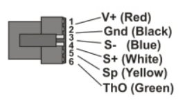
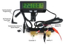
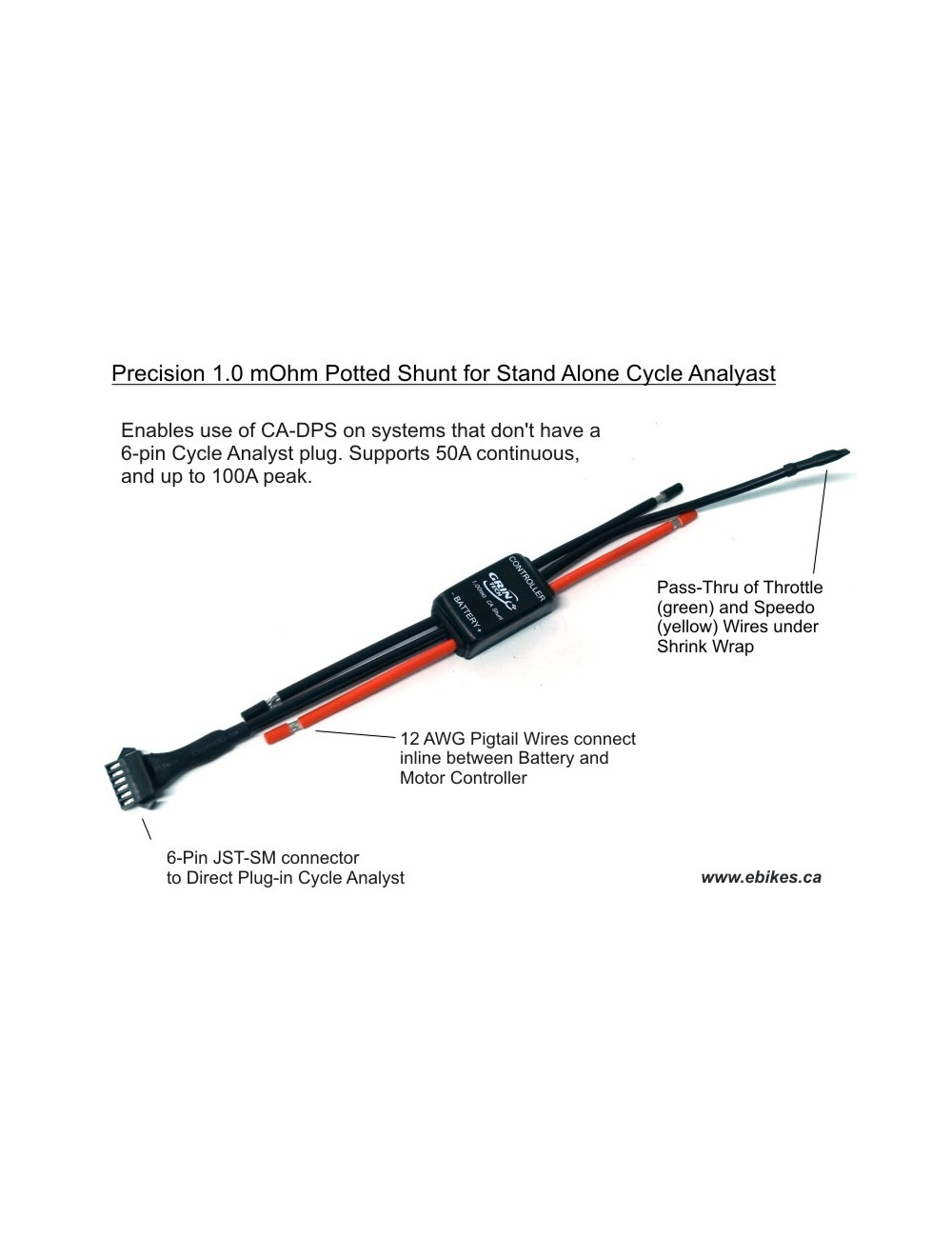
Is there a wiring diagram somewhere for the correct positioning of the shunt wiring for the ca plug? ( I would just pull apart the standard 50 amp shunt from Grin but it is potted).

I have found this https://ebikes.ca/pub/media/catalog/product/cache/7bc56b90756fa69927a10264ccfc611d/s/h/Shunt_Raw.jpg

which gives me an idea for some of it at least.

I am running a Castle Creations HC160 and CA3 with my CYC kit and want to reduce the bottle neck the small 10awg cables on the current shunt cause but I am struggling to find which wires go where?

I have a larger 200amp 50mv shunt arriving so I can add 8awg cables the same as the rest of the system.

Again,

Thank you
 
Ham said:
Is there a wiring diagram somewhere for the correct positioning of the shunt wiring for the ca plug? ( I would just pull apart the standard 50 amp shunt from Grin but it is potted).

I have found this https://ebikes.ca/pub/media/catalog/product/cache/7bc56b90756fa69927a10264ccfc611d/s/h/Shunt_Raw.jpg

which gives me an idea for some of it at least.

I am running a Castle Creations HC160 and CA3 with my CYC kit and want to reduce the bottle neck the small 10awg cables on the current shunt cause but I am struggling to find which wires go where?

I have a larger 200amp 50mv shunt arriving so I can add 8awg cables the same as the rest of the system.

this page may help
https://www.ebikeschool.com/add-cycle-analyst-connector-controller/
even though you aren't doing it that way, the wiring info in it still applies.

i dont' recall which order is which, but when you put the blue and white wires on each end of the shunt, and the black negative wire, putting them in one order gives you total system current, including the ca's own usage and anything connected to it, and the other excludes the ca and it's usage.

note that you need to switch the ca to hi range mode for your new shunt. this may affect or change other settings in the ca, so when you do this you should save all your settings first, then change the mode, then go thru all settings to be sure they are still correct for the operation you want from it. if behavior of system is undesirably different than before, it is likely one of the settings that is affected by the mode change.
 
Thank you,

I am struggling to make sense of that link tbh. I’ll keep searching and see what I can find…I just need to see the rest of that pic from the grin site…pictures are worth a thousand words and all that😀
 
Ham said:
Thank you,

I am struggling to make sense of that link tbh. I’ll keep searching and see what I can find…I just need to see the rest of that pic from the grin site…pictures are worth a thousand words and all that😀
Not exactly sure what the question is, but maybe these two diagrams would help:

CA connect.jpg

CA Shunt.jpg

Shunt looks to be placed in series with the ground/negative battery cable, with the white wire on the battery side, and the blue on the controller side. Apologies if I didn't understand the question. S(-) vs S(+) appear to reflect the direction of the current flow.
 
Ok it's making more sense now i think...

Black blue and white on battery neg side on the shunt.

Red is spliced into the battery pos. to power the ca3?

Yellow does nothing for mine.

Green (and yellow i guess) runs straight through to the throttle input on the controller without any connection to the shunt... this confused me as the standard 50 amp shunt is potted so i couldn't tell what ran straight through it and what was connected....

https://ebikes.ca/pub/media/catalog/product/cache/7bc56b90756fa69927a10264ccfc611d/s/h/Shunt-CA3.jpg

Shunt-CA3.jpg


That's what's on there now and I'm sure those little 12awg wires add to my voltage sag.

Am i there yet?

😂
 
Ham said:
Ok it's making more sense now i think...

Black blue and white on battery neg side on the shunt.

Red is spliced into the battery pos. to power the ca3?

Yellow does nothing for mine.

Green (and yellow i guess) runs straight through to the throttle input on the controller without any connection to the shunt... this confused me as the standard 50 amp shunt is potted so i couldn't tell what ran straight through it and what was connected....

https://ebikes.ca/pub/media/catalog/product/cache/7bc56b90756fa69927a10264ccfc611d/s/h/Shunt-CA3.jpg

Shunt-CA3.jpg


That's what's on there now and I'm sure those little 12awg wires add to my voltage sag.

Am i there yet?

😂

I think so, but you can actually check the connections with a meter. Check between the battery or controller black wires and the corresponding pins on the CA connector and look for continuity/0 ohms.
 
OK so I got the new shunt wired in, flipped the range to high range (new shunt is 0.25mOhm...200amp 50mv.), changed the r shunt value to 0.2500mOhm and now I have some interesting riding experiences i.e.

The display now shows the amps as negative when demanding power (which I guess means I have the shunt back to front despite me trying to follow the correct orientation of wires?). I did zero the amps after the change.

Now the PAS in low setting (0.6kw) tries to throw me off the back in a wheelie and over runs for a second or two which is amusing if not a little hairy and the throttle response is really really slow to pick up unless I up the Again from the 45 I was using in low range to 150.

I think I read somewhere that the high range setting changes all setting by a factor of 10 so AGain of 50 in low range is 500 in high range? If that is so does that hold true for all other settings like throttle up rates, pas rate, fast rate, pas start and stop thresholds?

I did the same upgrade years ago on a tangent build but for the life of me can't find my notes or remember what I did!

TIA
 
Ham said:
The display now shows the amps as negative when demanding power (which I guess means I have the shunt back to front despite me trying to follow the correct orientation of wires?).
swap blue and white

dont worry about the settings until that's done; negative amps means the ca calculations cant be right for positive amp limiting/etc; once it's not negative it will probably work better.
 
Yup, switched the wires as you described, although I linked the black in with white previously which I hope is OK as it is just ground?

Bench test seems O.K. off to see if it sends me flying again!
 
OK well all seems much better again now, many thanks for all the help!

Now I just need to figure out a way for it to produce power in the opposite way that it does right now! :)

Due to it in effect being a power sensor and not a torque sensor it offers very little help where I want it most, right at the start off line low pedal rpms and instead it adds more power the faster I pedal as my power increases...kind of the exact opposite of shop bought PAS bikes. It's not a big problem in low gears but the higher the gear the slower the crank speed and less help just when you really need it off road.

Anyone else managed to play about with this to get it work this way around?

Previous controllers I have add allow the torque sensor to only become active after "x" crank rotations and then also the ability to ramp it up slowly so it doesn't loop you.
 
somewhere in this thread is a post or few about what you want; you set one of the values to negative watts per whatever; sorry i can't remember which one it is. :(

also if you have an actual torque sensor you can get better low end response beause there will be higher torque at lower speed depending onyour pedal gearing.

a cadence only sensor doesn't do the same thing, you could set it so a lower cadence gives a higher power and it rolls off as you pedal faster but that doesn't work like a regular bicycle.
 
I see there is a new Solar Firmware release but can't find any release notes or change logs anywhere for it - does anyone know where I can find them?

I think I saw a couple of new beta releases too?.....

Thanks.
 
Edited...being a tool. Sorted for now I believe...missed that the release notes were in the help folder!
 
justin_le said:
Yes, actually more to the point I'm strongly considering in the next update that we just drop the watts/Hwatt scaling factor and have it instead be Watts/Nm. This is actually the original implimentation of the CA3 way way in the early beta/alpha firmwares. It was switched over to being W/HW because we thought that would be a more straightforward parameter for people to understand (oh, it just doubles my power), but I think most people would prefer if the motor power scaled linearly with pedal torque regardless of RPM. Then the RPM is just an on/off gate, and it makes it easier to have torque assist at 0 rpm, and if after like half a second ifthere is still no pedal cadence detected then it would shut off the PAS. Probably not in 3.15, but likely in 3.2.

did anything ever come from this, I have read release notes and am struggling to see how to set this up?

Edit...I am a tool...release 3.2b1 I think
 
loaded the correct firmware to allow for PAS to work from standstill and it is much more usable...still some fine tuning I think with fast thresholds and pas uprates but muuuch better! Thank you
 
Hi CA fans....I have a question about Cycle analyst PAS setting.
In the PAS menu under Stop Threshold, it allows me to enter the amount of seconds the motor continues to move after pedaling has stopped. I tried to increase it to 3 or 4 seconds. I can enter in the number but when it saves it changes back down to 2 seconds. Why is 2 seconds the maximum about of time? Is there a way to increase it higher?
Thanks
 
If the version of firmware you have limits it to a certain amount for a particular setting, then that's as much as you get.

You could try different versions of firmware in the setup program on the computer and see what they let you enter (rather than on your CA so you don't screw up your settings while experimenting).

Then if you find one that lets you do longer times, you can then make sure all the *other* settings and fucntions you're using will *also* still work as you need them to in that version, and then flash your CA to that version and set it up as you need to.


As for why? Probably for safety reasons. Personally I think even half a second is too long; two seconds could cause a disaster in traffic, if the rider is distracted by traffic conditions or something and stops pedalling to stop powering (doesn't need to brake) and then because the bike didn't stop powering/accelerating they crash into something unavoidable that's still moving in front of them becuase their brain tried to figure out why it was not behaving as they expected from "instinct" (if they learned riding on shorter times, or no assist).

If they never used any other system, then their base reactions would be learned from it, and their response would then be appropriate (to brake and cut power) but it's much more likely they'd've used a regular bicycle with no latency in response first, and learned to ride on that, long before, so those are the reactions their brain will go to first, in all likelihood.
 
Back
Top