Cycle Analyst V3 preview and first beta release

Gab said:
is it possible to implement a motor rpm counter and rev limiter ? to protect overvolted unloaded motors

I think it is essentially the same as a speed limiter, which is already available in V2.
 
While the MPH/KPH speed limiter could be used as an RPM limiter, I think he is asking for a separate one for whatever reason, that specifically reads out in RPM rather than MPH/KPH based on the wheelsize setting.

I can see a possible use for it: let's say you have a system that is limited to 20MPH for on-road assist, with a middrive setup of some type. But off-road it can have that limitation switched off. If it is a middrive setup (only time I can imagine overspeed happening; DD would be highly unlikely), off-road you could have it setup for such high performance that it could be possible to exceed the recommended RPM of the motor or some other part of the drivetrain, especially if it can do regenerative braking downhill and you're already coasting so fast that it would exceed the motor RPM if braking were engaged (assuming a mechanical clutch rather than freewheel or solid connection).

For my own case, I would simply setup external electronics that would cut off controller power or disconnect the motor clutch, or both, or whatever, in case of anything that could cause overspeed condition, before it actually lets the motor get near that. But it might be a lot easier to let the CA do it if you're experimenting and want to change the values a lot.


There might be other reasons to want this feature, but that's all I can come up with at the moment.
 
His question implies that an unloaded motor will run away speedwise like an IC engine. If this is the concern, it is of course not the case so perhaps there isn't a problem here that needs to be solved with a speed limiter.
 
I hadn't thought of that psosible problem, but if it's a series-wound brushed motor, it can indeed run away when unloaded. I know of at least one DIY car conversion that exploded the commutator from doing this.

If he wants to use the CA to control something with one and a transmission that could go into neutral, I guess it might be a helpful feature there too.
 
i would use the rev limiter, to stop the motor going over the max safe erpm of a kelly KEB (that should but doesn't have its own limiter)
 
I just replaced my Bombers small CA with a new 2.3 large bar mounted CA and it rocks....I can now see it! :)

One change I would love to see on V3.0 is on the main screen would be to replace AH's used with WH's used.

I want to see my (gas tank) without having to go two screen deeper and then back just to see if I need to turn for home.
 
amberwolf said:
I hadn't thought of that psosible problem, but if it's a series-wound brushed motor, it can indeed run away when unloaded. I know of at least one DIY car conversion that exploded the commutator from doing this.

If he wants to use the CA to control something with one and a transmission that could go into neutral, I guess it might be a helpful feature there too.

Yepper. I assumed, possibly incorrectly, a DC or DC brushless motor...
 
hi guys should of added more detail. this is for a brushless middrive setup. i have heard of occurrences of the magnets shatering at high rpm and the way too high rpm could happen is dowhill or too low a gear hence not enough load. do you think this is possible to show motor rpm in the ca? or should i try and find a controller to do the rpm limiter ?
 
Gab said:
hi guys should of added more detail. this is for a brushless middrive setup. do you think this is possible to show motor rpm in the ca? or should i try and find a controller to do the rpm limiter ?
Foregoing the question of whether you need rev limiting or not - if you wish to keep an eye on RPM:

  • Since you are using a mid-drive setup, you will be using a wheel pickup for your speed sensor instead of the controller DP/Sp connection to eliminate the effect of varying gear ratios.

    I'm just winging it here, but I believe you might be able to re-purpose the unused yellow speed (Sp) wire from the controller DP connector as an input to the PAS PCB pad. Then go into Setup and configure the PAS poles to match you motor pole count. If you leave Ctrl->PASMode=PASOff, this should not affect CA operation but the RPM displays should then reflect motor instead of crank speed. (Unfortunately, I have non-standard cabling (no CA-DP/Sp connection) and it's a PITA to get into my CA so I can't test this - Justin will need to verify this hack will work...)
This will not get you rev limiting but it should get you a motor RPM display.

Earlier in this thread there was discussion of customizable display(s) so at some point the RPM (or other desirable value e.g. Wh) should be able to be prominently displayed on the main screen.
 
One of the things you can do since the CA is limited to 4 digit mm wheel sizes is that you could scale your max RPM to max speed on the CA (99mph or kph?).. then you always have the percentage of full rpm on screen.

Example: 1000 is peak RPM, 99 is 99 mph displayed. x is diameter in mm. The mph setting will offer more resolution I believe.
1000*((x)/25.4)*60/12/5280=99

x=2655

compensation for that last 1mph

(1000-.01*1000)*((x)/25.4)*60/12/5280=99

Just a thought. Some people don't need a speedo to tell how fast they're going.
I was just thinking how this might be particularly useful for those of use who want to know exactly what part of the efficiency curve they are in
 
As hillzoflap just said, the other reason it would be nice was to know where abouts i am in the RPM efficiency window, hence if RPM was displayed on the screen with all the other data then we could throttle and change gears to get max efficency. is it possible to add another speed sensor and not repurpose the road speed sensor? becuase i will loose the functionality. Since the CA already connects to the throttle for current limiting then it would be ideal if it also did RPM display limiting for mid drives.
 
Gab said:
As hillzoflap just said, the other reason it would be nice was to know where abouts i am in the RPM efficiency window, hence if RPM was displayed on the screen with all the other data then we could throttle and change gears to get max efficency. is it possible to add another speed sensor and not repurpose the road speed sensor? becuase i will loose the functionality. Since the CA already connects to the throttle for current limiting then it would be ideal if it also did RPM display limiting for mid drives.

Looks to me you could attach a magnet to the largest gear driven by the motor directly to measure rpm. Then change the settings in the CA to 1 magnet and wheel circumference 1, effectively showing you rpm.

Do you really think that you will keep looking at the screen while shifting gears and try to get max efficiency? I would rather look outside to traffic, nature, and beautiful women.
 
hjns said:
Do you really think that you will keep looking at the screen while shifting gears and try to get max efficiency? I would rather look outside to traffic, nature, and beautiful women.
+1 :D

FWIW: A quick search of ES for 'rev limiter' doesn't bring much up. A cheap tach or tach module hooked to the controller CA-DP/Sp signal (with a transistor driver if necessary) may be the easiest display solution, but again - see hjns remark above...
 
Justin, I'm a month and a half late in posting this (I've been out of town) but build 17 of the code seems to be working nearly perfectly on my hubmotor bike using current throttle. No more surging, no more miscalibration. The only oddity I have noticed (and this is an exceedingly trivial thing) is that when I review my post-ride data, the MaxS display shows a very high number. At the moment, for instance, it shows "334." MPH.

It's always done this, but in the past I assumed that it was directly correlated to the "runaway speedo at powerup" anomaly that existed when the user had "Miles" rather than "Kilometers" selected. And I did check to see that, unlike before, the MaxS value is not becoming corrupted immediately at powerup- it happens during the ride.

Come to think of it, I have not tried doing a full ride in "Kilometers" mode on build 17 to see if there's still some relationship there. I've just changed units and reset the log, and I will see what it does on the way home this afternoon.
 
Joe Perez said:
Justin, I'm a month and a half late in posting this (I've been out of town) but build 17 of the code seems to be working nearly perfectly on my hubmotor bike using current throttle. No more surging, no more miscalibration. The only oddity I have noticed (and this is an exceedingly trivial thing) is that when I review my post-ride data, the MaxS display shows a very high number. At the moment, for instance, it shows "334." MPH.

It's always done this, but in the past I assumed that it was directly correlated to the "runaway speedo at powerup" anomaly that existed when the user had "Miles" rather than "Kilometers" selected. And I did check to see that, unlike before, the MaxS value is not becoming corrupted immediately at powerup- it happens during the ride.

Come to think of it, I have not tried doing a full ride in "Kilometers" mode on build 17 to see if there's still some relationship there. I've just changed units and reset the log, and I will see what it does on the way home this afternoon.

Are you using the separate reed switch speed sensor, or are you using hub motor commutation to compute speed?

While your problem may not be related, I discovered that with the later models of the CycleAnalyst I would get high MaxS (maximum speed) readings occasionally, between 300 and 650 mph when this occurs.

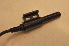
I tracked it down to the concurrence of two things. The newer CycleAnalysts use a reed switch pickup that is sensitive to high-frequency vibration that occurs when the rim brake on the sensored wheel, usually the front wheel, squeals.

DSCF4292.jpg

On one of my bikes I replaced the reed switch with one off of an old DrainBrain and discovered that the spurious MaxS readings ceased. Unfortunately, according to Justin this older style reed switch is no longer available.

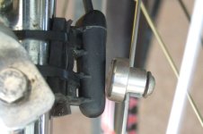
DSCF4289.jpg

I tried using a reed switch off of another bike computer kit, and it is less sensitive to brake squeal, but it still occasionally gives a spurious MaxS if the front brake squeal is especially severe. The switch is anchored along most of its length, but the mount itself is cantilevered out from the fork, which may explain why it is still susceptible.


I haven't done an exhaustive search of available reed switches used for bicycle computers, but there may be a switch out there that is not sensitive to squeal. I suspect that a reed switch that is not cantilevered, that is anchored at both ends or along its entire length and is not itself cantilevered out from the fork is less likely to exhibit the high-frequency resonance that leads to spurious speed readings.

Why don't I adjust my brakes so that they don't squeal?

Well, I do. But I ride in an area that often has enough humidity to produce moisture on the rim braking surface, and this can lead to squeal even with properly adjusted brake shoes. Sometimes squeal is unavoidable.
 
mrbill said:
While your problem may not be related, I discovered that with the later models of the CycleAnalyst I would get high MaxS (maximum speed) readings occasionally, between 300 and 650 mph when this occurs.

I tracked it down to the concurrence of two things. The newer CycleAnalysts use a reed switch pickup that is sensitive to high-frequency vibration that occurs when the rim brake on the sensored wheel, usually the front wheel, squeals.
I am using the same reed pickup that I used with my V2 and have had similar spurious high speed readings from the outset. This never occurred with my V2. The spurious changing high speed readings on the V3 go on for a period of time with no brake application and at slow rolling speed on pavement or even for a bit after a stop. For my bike, these incidents do not appear related to the pickup.

At this point I believe the operative theory is that this may be related to the similar spurious HumanPower/RPM readings mentioned in this post. Justin added an extra Cycle Analogger field (Limiting Factor) to provide additional data and incidents with both types of wonky readings have been captured for analysis.

These are slippery little buggers to track down, especially since the incidents are intermittent and the afflicted bikes are remote, so any problem reports Justin can get are of particular value in providing clues to resolution.
 
Something to watch for - the newer reed switch casing is a cantilever. It could be that snubbing the free end to kill any vibration at the natural frequency of this cantilever would also eliminate the contact chatter.
 
The maxS reading occurs when the CA hangs up for a few seconds. The clue that it is occurring is that on the main screen the torque sensor bar starts jumping a bit.
Then if you go through the readings you will find that there are high rpm and torque sensor readings. The maxS is also corrupted with these readings. B17 & I don't use the torque sensor input.
 
Interesting- I hadn't considered the possibility of simply a noisy sensor signal due to mechanical vibration.

The pickup I am using is of the style shown in Mr Bill's first image. I have disc brakes rather than rim brakes, and the magnet/sensor are located roughly halfway between the hub and the rim. The sensor is mounted to the front fork in such a way that vibration is certainly possible- a couple of zip-ties hold it to the fork, and a piece of rubber inner-tube is between the sensor body and the fork to prevent the sensor from trying to rotate around the fork.

This might simply call for a bit of capacitance across the two sensor leads to create an absurdly long time-constant. Does anybody happen to know the value of the pullup resistor on the sensor line?
 
yep, i have super high kph readings from that extended plastic casing type reed, its solid on the rear and its not to do with squeal, -tried a .1uf cap without any luck, maby they are not so good.
nevermind if you allready have thousands in stock ready to go justin. :lol:
 
Oh boy... Matthew and I just got a big box full of V3 CA's... looks like I have 40 pages of catching up to do :mrgreen:
Excited to try out the new features.

When I was here 20 pages ago I mentioned our Arduino Shield (GizMo) - it is currently being fabricated at the board house and will be here in a couple weeks. If there are any Arduino fans out there who would like to start working on interfacing with the CA V3 (any ideas welcome - I have nothing specific in mind) shoot me a PM and on our next spin we can work in any additional interfaces that you need.

We already have an RTC, micro SD, USB (and all of the usual arduino stuff), RTD's, wireless temp, hall current sensing, RPM, and other things I have forgotten. Some of this overlaps with CA functionality but some of it does not... I would really like to see what people can come up with.

-methods
 
methods said:
Oh boy... Matthew and I just got a big box full of V3 CA's... looks like I have 40 pages of catching up to do :mrgreen:
Excited to try out the new features.

We already have an RTC, micro SD, USB (and all of the usual arduino stuff), RTD's, wireless temp, hall current sensing, RPM, and other things I have forgotten. Some of this overlaps with CA functionality but some of it does not... I would really like to see what people can come up with.

-methods

Could u elaborate on what this gizmo will do? Just logging? Confused. Maybe there's a thread somewhere?
 
Hi Justin,

My CAv3 b16 just stopped working. When I power on, the CA goes through boot, and then shows only a horizontal row of rectangles. Powering off and then on again results in the same. Should I try to flash? Any other suggestions?

I am running 20S (84V HOC, 74V nominal, 73V LVC programmed in another CAv2), with a CAv2 running a current throttle and an 18FET 4110 from Lyen. The controller is limited to 80A/210A with 100% speed setting and regen enabled at it's strongest. The CAv2 is limited to 80A 100km/h and plugged into the controller using a DP. The CAv3 is connected to an external shunt as recommended in the CA manual for external shunts (aka in line with the controller on the ground side). The CAv3 is also connected to the thermistor in my cromotor and to the CA analogger. The other connectors are not connected.

I am open for any suggestions!
 
hjns said:
My CAv3 b16 just stopped working. When I power on, the CA goes through boot, and then shows only a horizontal row of rectangles. Powering off and then on again results in the same. Should I try to flash? I am open for any suggestions!
I haven't seen this particular boot failure display symptom (mine is always blank with backlight on)...

Thoughts:
  • The v3b16 firmware file is known to be corrupted. I would immediately upgrade to a more contemporary build (v3b17) to get onto a firmware base that is known to be uncompromised. Although your CA may have been operational, the actual code it is running is unknown and hence any symptom reports are of little value.
  • When the boot-failure issue occurs for me, it is necessary to remove the power (bike/CA) so that the CA is restored to a completely idle and inoperative condition. This can take a minute or so if the voltage is high and the CA remains connected to the controller after the power connection is severed. Failure to get to a full-power-down state invariably prevents proper reboot.
  • I run my battery cutoff setting fairly high (e.g. for 66v nominal: Batt->VltCutoff=40v) to ensure that the CA has ample power/time to tidy up before shutdown.
 
Back
Top